
Sunfire L4-2.2L VIN 4 (1996)
Powertrain Control Module: Description and Operation
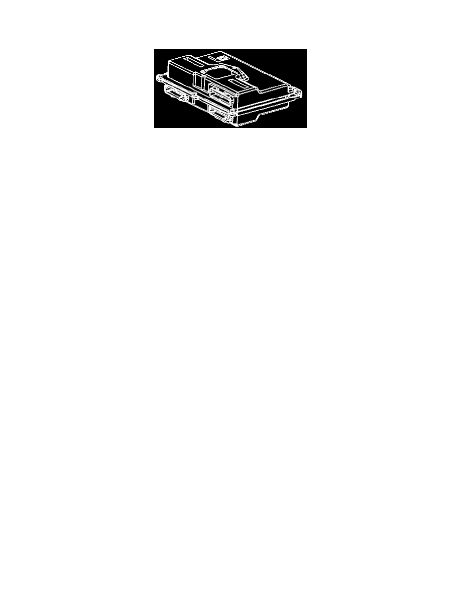
Powertrain Control Module (PCM)
Powertrain Control Module (PCM)
DESCRIPTION
The Powertrain Control Module (PCM), located under the right front fender; is the control center of the fuel injection system. It constantly looks
at the information from various sensors, and controls the systems that affect vehicle performance. The PCM also performs the diagnostic function
of the system. It can recognize operational problems, alert the driver through the Malfunction Indicator Lamp (MIL) (Check Engine), and store a
DTC or DTCs which identify the problem areas to aid the technician in making repairs.
The PCM used on this vehicle is referred to as PCM-6SU. For service, this PCM only consists of two pans: a controller (the PCM without a KS
module) and Knock Sensor (KS) module.
EEPROM
This assembly contains the functions of the Electronically Erasable Programmable Read Only Memory (EEPROM) and is a permanent part of the
PCM. The EEPROM contains the calibrations needed for a specific vehicle application and is service only through a re-programming procedure.
OPERATION
The Powertrain Control Module (PCM) supplies either 5 or 12 volts to power various sensors or switches. This is done through resistance's in the
PCM which are so high in value that a test light will not light when connected to the circuit. In some cases, even an ordinary shop voltmeter will
not give an accurate reading because its resistance is too low. Therefore, a 10 megohm input impedance digital voltmeter is required to assure
accurate voltage readings.
The Powertrain Control Module (PCM) controls most components with electronic switches which complete a ground circuit when turned "ON."
These switches are arranged in groups of 4 and 7, called either a surface mounted Quad Driver Module (QDSM), which can independently control
up to 4 outputs (PCM) terminals or Output driver Modules (ODMS) which can independently control up to 7 outputs. Not all outputs are always
used.
CLASS II SERIAL DATA
U.S. Federal regulations require that all automobile manufacturers establish a common communications system. General Motors utilizes the Class
II communications system. Each bit of information can have one of two lengths: long or short. This allows vehicle wiring to be reduced by the
transmission and reception of multiple signals over a single wire. The messages carried on Class II data streams are also prioritized. In other
words, if two messages attempt to establish communications on the data line at the same time, only the message with higher priority will continue.
The device with the lower priority message must wait. The most significant result of this regulation is that the regulation provides scan tool
manufacturers with the capability of accessing data from any make or model vehicle sold in the United States.
PASSWORD LEARN PROCEDURE
In order for a theft deterrent vehicle to run, a password is communicated between the Instrument Panel Cluster (IPC) and the PCM. If a PCM is
replaced, the new PCM needs to learn the correct password of the vehicle. When the new PCM is installed, the EEPROM calibration is flashed
into the new PCM and the vehicle will learn the new password upon initial ignition ON. If the IPC is replaced, the PCM needs to learn the new
password from the IPC. The password learn procedure is as follows:
1. Attempt to start vehicle, then leave the ignition ON. The THEFT SYSTEM telltale will flash for 10 minutes.
2. When the THEFT SYSTEM telltale stops flashing, start the vehicle. Once the vehicle is running, the password is learned.