
Torrent AWD V6-3.4L VIN F (2006)
Install the 2 bolts (5) that secure the EGR pipe (4) to the exhaust manifold.
Tighten
Tighten the EGR pipe assembly bolts to 10 N.m (89 lb in).
Install the bolt (3) the secures the EGR pipe (4) bolt to the EGR valve (1).
Tighten
Tighten the bolt to 30 N.m (22 lb ft).
In the following steps, care must be taken to prevent cross-wiring of the two gray colored EGR wire leads (located at pin A and pin D). Cross-wiring will
result in an MIL to be set. Before cutting the wiring harness leads, mark the gray leads using tape so the location will be remembered on assembly.
Take the disconnected EGR valve harness electrical connector and cut the wires directly at the base of the connector. Open the EGR electrical conduit to
expose the wire leads.
Strip approximately 6 mm (1/4 in) of insulation from all five EGR circuit harness connector wires.
Refer to the correct EGR Valve Wiring Harness Connector End View Schematics in the bulletin for the installation of the new EGR valve wiring harness
connector, P/N 15306175.
Use splice seal connectors supplied in the wiring harness kit (P/N 15306175) when replacing the EGR valve wiring harness connector.
Install the new EGR valve wiring harness connector, P/N 15306175 (includes splice connectors, terminals and wire leads), to the existing engine wiring
harness.
Use a heat gun to shrink the tubing and set the glue in the connectors.
Wrap the new EGR valve wiring harness leads with electrical tape and secure them into the EGR valve electrical harness conduit.
Failure to correctly wire the EGR valve electrical connector will result in a PCM diagnostic code to set and result in a "Service Engine Soon" indicator
lamp to illuminate.
Connect the engine harness electrical connector to the EGR valve.
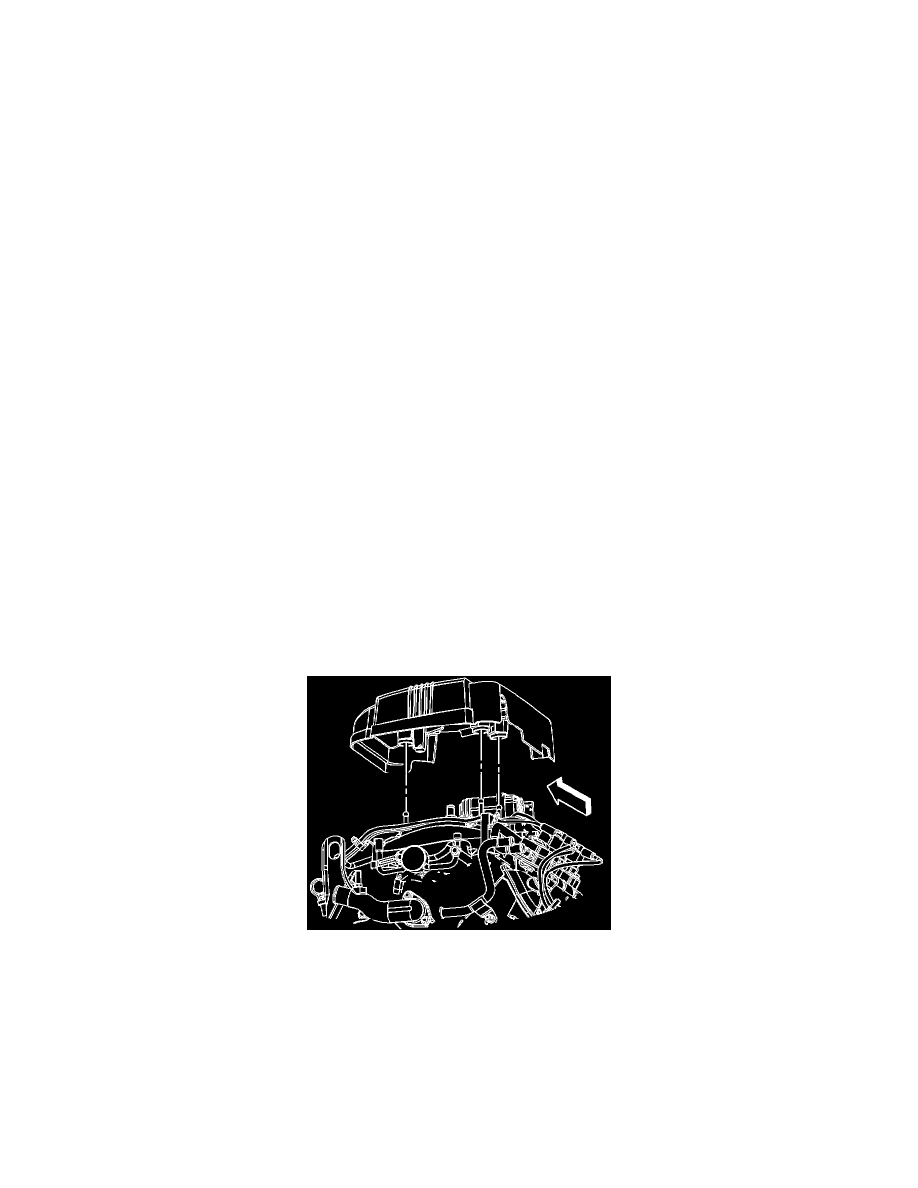
If equipped, install the injector sight shield to the studs.
Connect the negative battery cable at the battery.
Reprogram the PCM with the latest calibrations for the EGR system change over. This calibration, or any that follow, is designed to address this concern.
Refer to Service Programming System (SPS) using the appropriate Service Information (SI) procedures. The PCM calibrations are available to
dealerships as part of TIS2000 incremental satellite update version 1.0, which was broadcast to dealers January 08, 2006 or later. For the dealerships that
use CDs, they were mailed out January 14, 2006 or later. As always, make sure your Tech 2(R) is updated with the latest software version.