
Torrent AWD V6-3.4L VIN F (2006)
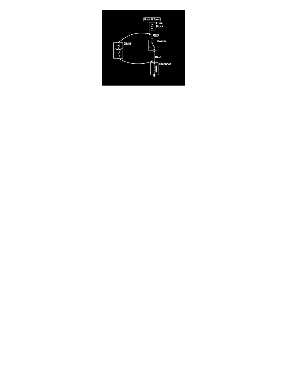
1. Set the rotary dial of the DMM to the V (DC) position.
2. Connect the positive lead of the DMM to 1 point of the circuit to be tested.
3. Connect the negative lead of the DMM to the other point of the circuit.
4. Operate the circuit.
5. The DMM displays the difference in voltage between the 2 points.
Probing Electrical Connectors
PROBING ELECTRICAL CONNECTORS
IMPORTANT: Always be sure to reinstall the connector position assurance (CPA) and terminal position assurance (TPA) when reconnecting
connectors or replacing terminals.
Frontprobe