
Trans Sport V6-3800 3.8L (1994)
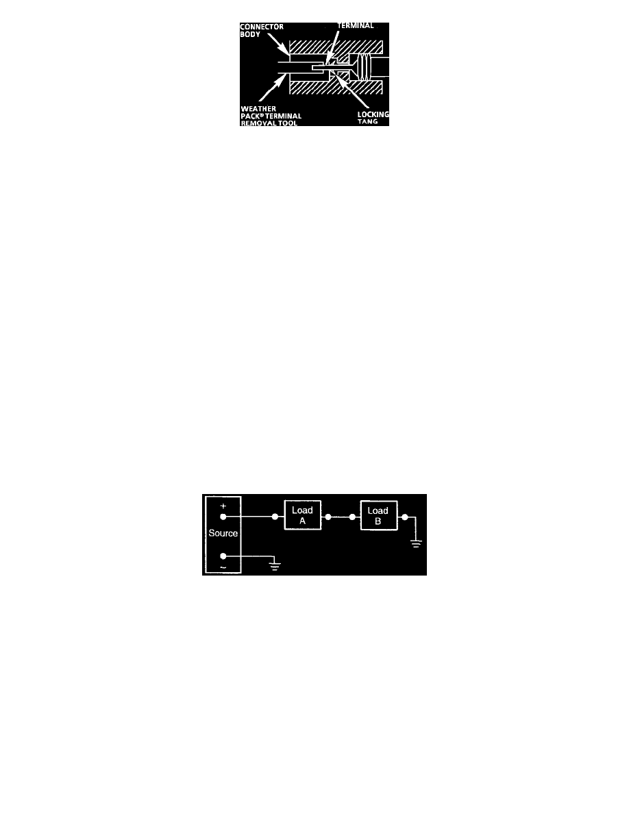
Fig. 21 Typical Weather Pack Connector and Terminal
Follow the steps below to repair Weather Pack(R) connectors, Fig. 21.
Step 1:
Separate the connector halves.
Step 2:
Open secondary lock. A secondary lock aids in terminal retention and is usually molded to the connector.
Step 3:
Grasp the lead and push the terminal to the forward most position. Hold the lead at this position.
Step 4:
Insert the Weather Pack(R) terminal removal tool into the front (mating end) of the connector cavity until it rests on the cavity shoulder.
Step 5:
Gently pull on the lead to remove the terminal through the back of the connector.
NOTICE: Never use force to remove a terminal from a connector.
Step 6:
Inspect the terminal and connector for damage. Repair as necessary, see TERMINAL REPAIR.
Step 7:
Reform the lock tang and reseat terminal in connector body.
Step 8:
Close secondary locks and join connector halves.
Electricity
Electrical power flows from the power source to a load device and then back to the source of power. The electrical circuit should contain a device
to open or close the circuit, such as a switch or relay, and a protective device (in case of an overload), such as a circuit breaker or a fusible link.
Electrical circuits can be set up as series circuits, parallel circuits, or series/parallel circuits. The circuits in this vehicle are normally parallel
circuits.
Series Circuit
Series Circuit
In a series circuit, the electrical devices are connected to form one current path to and from the power source. In a series circuit the voltage is
shared equally by all the devices in the circuit.
Parallel Circuit