
Vibe L4-1.8L VIN L (2003)
Tools Required
^
J 45101-100 Conical Brake Rotor Washers
Adjustment Procedure
Important: Brake rotor thickness variation greater than the specification can cause brake pulsation.
1. Measure the brake rotor thickness variation. Refer to Brake Rotor Thickness Variation Measurement.
Important: Brake rotor assembled lateral runout (LRO) greater than the specification can cause brake pulsation.
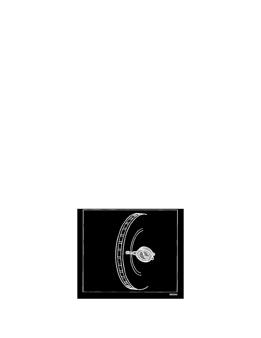
2. Measure the brake rotor LRO. Refer to Brake Rotor Assembled Lateral Runout (LRO) Measurement.See: Testing and Inspection/Component
Tests and General Diagnostics/Brake Rotor Assembled Lateral Runout (LRO) Measurement
3. Remove the J 45101-100 and the wheel nuts.
4. Remove the rotor from the hub.
5. Rotate the rotor 1 wheel stud position (72 degrees).
6. Install the rotor to the hub.
7. Hold the rotor firmly against the hub. Install one of the J 45101-100 and 1 wheel nut on the top wheel stud.
8. Continue to hold the rotor and tighten the wheel nut by hand.
9. Install the remaining J 45101-100 and the wheel nuts.
10. Tighten the wheel nuts firmly by hand in a star pattern.
Notice: Refer to Fastener Notice in Cautions and Notices.
11. Tighten the wheel nuts in a star pattern in order to retain the rotor to the hub. Refer to Fastener Tightening Specifications in Tires and Wheels.
12. Measure the brake rotor LRO. Refer to Brake Rotor Assembled Lateral Runout (LRO) Measurement.
13. If the brake rotor LRO is greater than the specification, repeat this procedure with the rotor at the remaining 3 wheel stud positions.
14. If the brake rotor LRO is greater than the specification at all 5 wheel stud positions, use an on-vehicle lathe in order to reduce the brake rotor LRO
to the specification. Refer to Brake Rotor Assembled Lateral Runout (LRO) Correction - On- Vehicle Lathe. See: Brake Rotor Assembled Lateral
Runout (LRO) Correction Methods/On Vehicle Lathe
15. If the brake rotor LRO is less than the specification, complete the following steps:
^
Use paint in order to mark the position of the brake rotor on the hub.
^
Install the brake caliper.
^
Press the brake pedal several times in order to position the brake rotor.
^
Remove the wheel nuts.
^
Remove the J 45101-100.
^
Install the tire and wheel assemblies. Refer to Tire and Wheel Removal and Installation in Tires and Wheels.
Correction Plates
Brake Rotor Assembled Lateral Runout (LRO) Correction
Adjustment Procedure