
Vibe L4-1.8L VIN L (2003)
Steps 8-13
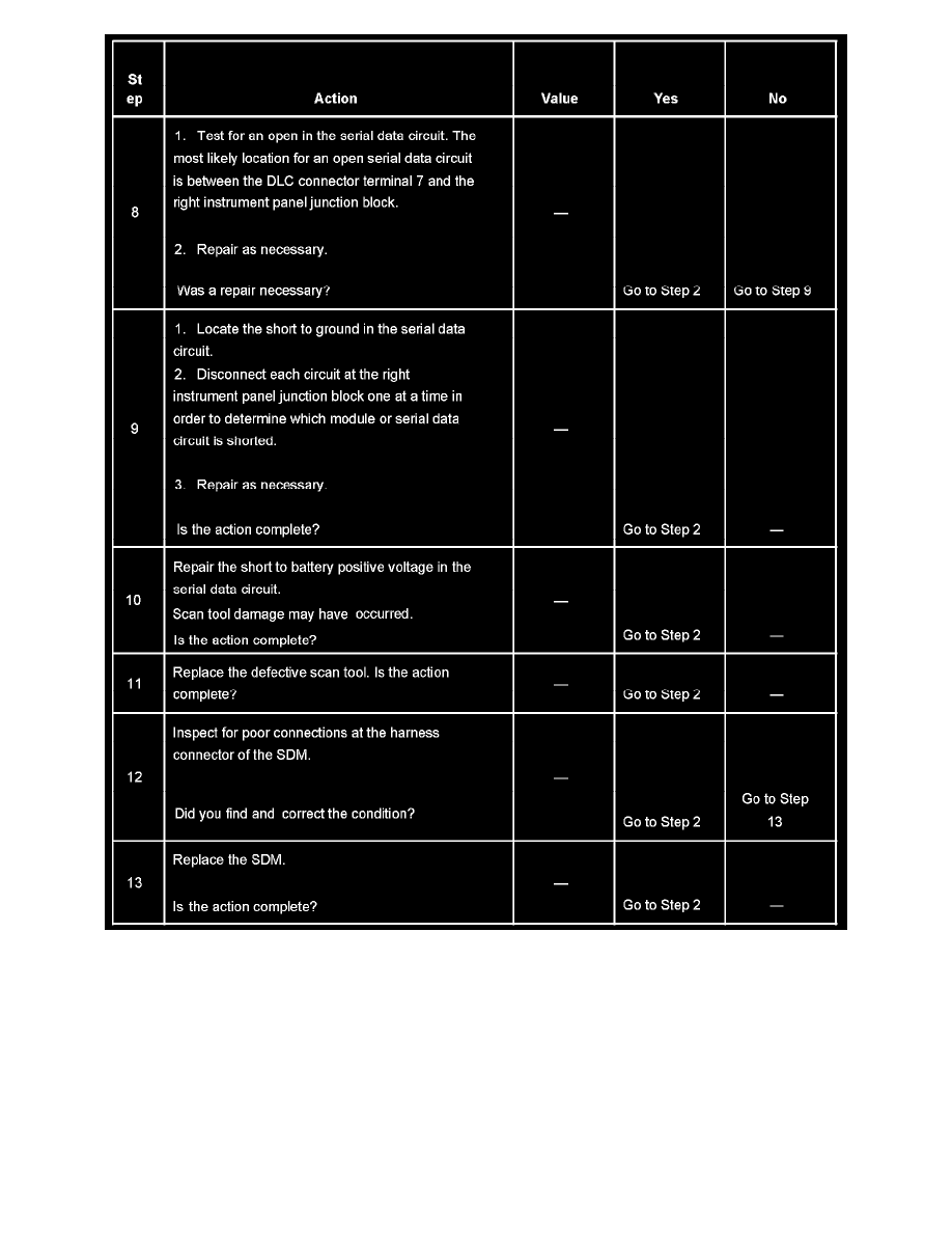
The numbers below refer to the step numbers on the diagnostic table.
4. This step checks whether the scan tool can communicate with other control modules on the vehicle. If the scan tool can communicate with the
Power Train Control Module (PCM), then the DLC ground circuit (terminal 4) and the DLC ignition positive voltage circuit (terminal 16) are OK.
5. This step checks for an open in the serial data circuit between the SDM and the right instrument panel junction block or for a defective SDM.
6. This step checks for an open/short to ground circuit, a short to battery positive circuit, or for a defective scan tool.
7. The modules supply a low current (about 1.85 mA) on the serial data circuit. The normal circuit low current will NOT illuminate a test lamp. If the
circuit is shorted to battery positive the higher current will illuminate the test lamp.
10. The scan tool may be damaged by high current flow on the serial data circuit at DLC terminal 7. Verify the scan tool for proper operation on a
known good vehicle that uses terminal 7 of the DLC for serial data communication.
Scan Tool Does Not Communicate With VCM/PCM
SCAN TOOL DOES NOT COMMUNICATE WITH VCM/PCM