
Vibe L4-1.8L VIN L (2003)
Engine Control Module: Service and Repair
REMOVAL PROCEDURE
NOTE:
-
Check the resistance values of all PCM relays, solenoids, and other output controls before replacing or substituting the Powertrain Control Module
(PCM). Check all the sensor wiring and the PCM output control circuits for a short to ground before replacing or substituting the PCM. Perform
all circuit repairs or malfunctioning component part replacements before installing a replacement or substitute PCM. This will prevent damage to
the replacement or substitute PCM.
-
Do not touch the connector pins or soldered components on the circuit board in order to prevent possible electrostatic discharge (ESD) damage to
the PCM.
-
Turn the ignition OFF when installing or removing the PCM connectors and disconnecting or reconnecting the power to the PCM (battery cable,
PCM pigtail, PCM fuse, jumper cables, etc.) in order to prevent internal PCM damage.
IMPORTANT: Service of the powertrain control module (PCM) consists of a complete replacement of the PCM. There are no serviceable parts,
such as programmable read-only memory (PROM) or erasable programmable read-only memory (EPROM) to replace inside the PCM. If the PCM is
determined to be faulty, the PCM is to be replaced as a complete assembly.
1. Disable the supplemental inflatable restraint (SIR) system. Refer to SIR Disabling and Enabling Zones in Restraint Systems.
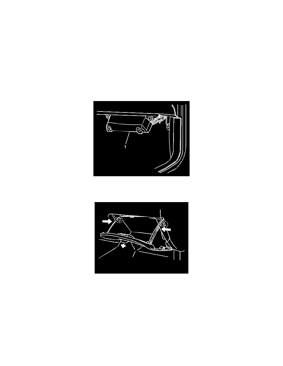
2. Remove the 2 retainers from the PCM close out panel (1) below the instrument panel (I/P) compartment door.
3. Swing the PCM close out panel (1) down.
4. Open the I/P compartment.
5. Push in on both sides of the I/P compartment in order to release the safety catches.
6. Remove the I/P compartment door assembly from the I/P.