
Vibe L4-1.8L VIN L (2003)
Ignition Relay: Testing and Inspection
IGNITION RELAY DIAGNOSIS
CIRCUIT DESCRIPTION
The ignition relay, also called the EFI relay, provides ignition positive voltage to the control module and other engine control components anytime the
ignition is ON. One side of the coil of the EFI relay is always grounded. The relay is energized when the ignition switch applies voltage to the other
side of the coil. The switch side of the EFI relay receives powered from the EFI fuse in the fuse block.-underhood. When the coil is energized, a
magnetic field closes the switch side of the relay, supplying power to the following engine components:
-
Circuit opening relay, also called the fuel pump relay.
-
Heated oxygen sensors (HO2S)
-
Mass air flow (MAF) sensor
-
Evaporative emission (EVAP) control system solenoids
-
Idle air control (IAC) valve
-
Powertrain control module (PCM)
DIAGNOSTIC AIDS
Check for any of the following conditions:
-
Check the resistance of the EFI relay. There is continuity across terminal 1 and terminal 2. The resistance across terminal 5 and terminal 3 is
infinite.
-
The EFI relay electrical contacts may be pitted or sticking. Replace the EFI relay if tapping gently on the relay or wiggling the relay causes a
change in the relay's operation.
-
The performance of the EFI relay may be affected by temperature. Check the EFI relay after sitting outside overnight and after running the engine
30 minutes.
-
If the EFI fuse opens during cranking, check for a shorted fuel pump/circuit. The EFI relay supplies current to the circuit opening relay that
supplies power the fuel pump. The circuit opening relay is energized during cranking and when reference pulses are detected by the PCM.
An intermittent malfunction may be caused by a fault in the EFI relay electrical circuit. Inspect the wiring harness and components for an intermittent
condition. Refer to Intermittent Conditions. See: Powertrain Management/Computers and Control Systems/Testing and Inspection/Initial Inspection
and Diagnostic Overview/Diagnostic Strategies
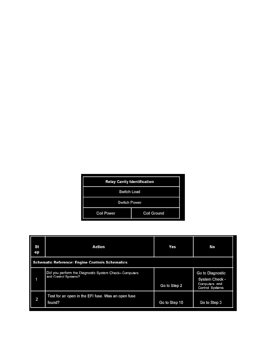
Use the following relay cavity table in order to locate the correct cavities to probe during diagnosis. The table layout corresponds to the cavity layout
of the relay block.
TEST DESCRIPTION
Steps 1-2