
Vibe FWD L4-1.8L VIN 8 (2004)
-
The HO2S heater circuits
-
The KS system
-
The CPU in the PCM
-
The fuel cut-off for ignition system failures
Control Module Learning Ability
The powertrain control module has a "learning" ability which enables the control module to make corrections for minor variations in the fuel system.
This learning ability can improve driveability. Disconnecting the battery resets the learning process. A change in the vehicle's performance may be
noticed when a reset from a PCM power down occurs. Operating the vehicle under varying conditions will enable the control module to regain any
lost vehicle performance.
In order to initiate the control module learning ability, warm the engine to operating temperature and drive the vehicle at part throttle with moderate
acceleration. Continue to drive the vehicle while including steady cruise and idle speed operation. For the best idle speed quality several key cycles
with a short drive and long idle periods is recommended.
Check Mode
The PCM has the ability to operate in the Normal mode or in the Check mode. The 2 modes of operation are similar. When the PCM is operating in
the Check mode, the PCM has an increased ability to detect malfunctions. The most significant feature of the Check mode operation is that all B type
codes now run like A type codes. In order to request that the PCM operate in the Check mode, scan tool communication with the PCM is necessary.
For information on the use of the Check Mode in diagnosing driveability concerns, refer to Service Bay Test.
PCM Output Controls
The powertrain control module (PCM) can be directed by a scan tool to operate certain solenoids, valves, motors, and switches. This scan tool
function is generally referred to as Output Controls. The Output Controls can be found under Special Functions selection of the scan tool. Some
Output Controls may be disabled by the PCM during certain types of vehicle operation. Operating a PCM controlled device with the scan tool should
be limited to a maximum of ten seconds per test period.
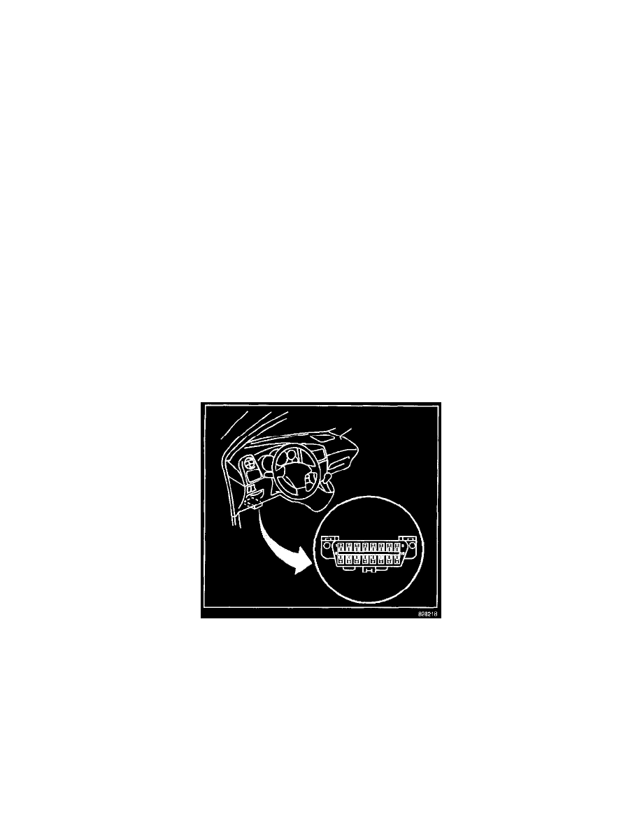
Data Link Connector (DLC)
IMPORTANT: Do not use a scan tool that displays faulty data. Report the scan tool problem to the manufacturer. Use of a faulty scan tool can result
in misdiagnosis and unnecessary parts replacement.
The provision for communicating with the control module is the data link connector (DLC). The DLC is located under the instrument panel to the left
of the steering column. The DLC is used to connect to a scan tool. Some common uses of the scan tool are listed below:
-
Identifying stored diagnostic trouble codes (DTCs)
-
Clearing the DTCs
-
Performing output control tests
-
Reading the serial data
Reading Diagnostic Trouble Codes
The procedure for reading diagnostic trouble codes is to use a diagnostic scan tool. Follow the instructions supplied by the scan tool manufacturer in
order to read DTCs accurately.
Clearing Diagnostic Trouble Codes
IMPORTANT: Do not clear the DTCs unless directed to do so by the service information provided for each diagnostic procedure. The Freeze Frame