
Vibe FWD L4-1.8L VIN L (2005)
Steps 17 - 18
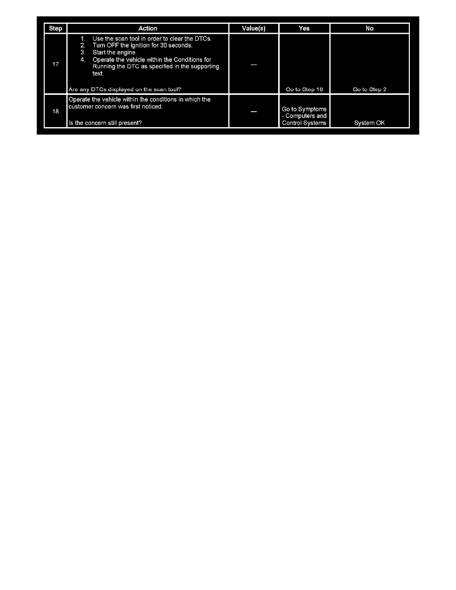
The numbers below refer to the step numbers on the diagnostic table.
1. A Diagnostic System Check-Vehicle prompts the technician to complete some basic checks and store the Freeze Frame data on the scan tool if
applicable. This creates an electronic copy of the data taken when the fault occurred. The information is then stored in the scan tool for later
reference.
4. This step tests whether the PCM can operate the IAC valve with the scan tool. The IAC valve can be commanded to increase and/or decrease
engine speed by using the scan tool RPM Control function. Remember to clear any DTCs and run the engine until the engine reaches a normal
operating temperature before attempting RPM Control with the scan tool.
5. This step checks the operation of both electrical load idle-up circuits. If there is no increase in the IAC Motor Command percentage when the
electrical accessory is turned ON, the idle-up circuit may be inoperative or always ON.
6. This step checks the operation of the A/C idle-up circuit. If there is no increase in the IAC Motor Command percentage when the A/C compressor
is engaged, the idle-up circuit may be inoperative or always ON.
10. This step simulates the pulse width modulated (PWM) signal supplied to the IAC valve by the PCM by rapidly grounding and un-grounding
terminal 1 of the IAC valve.
12. The most likely cause of no ignition positive voltage is an open circuit condition between the IAC valve connector terminal 2 and the splice. A
shorted or inoperative EFI relay circuit will cause a no-start condition.