
Vibe FWD L4-1.8L VIN L (2005)
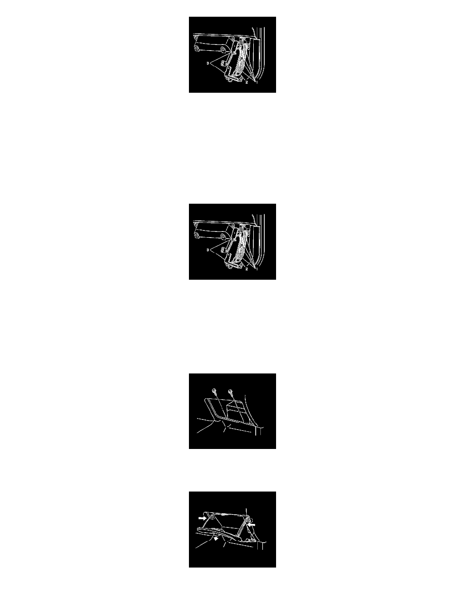
8. Pull the PCM (2) with brackets (3) toward you and swing both down away from under the IP.
9. Disconnect the four PCM electrical connectors (1).
10. Remove the four fasteners and the two brackets (3) from the PCM (2).
INSTALLATION PROCEDURE
NOTE:
-
Do not touch the connector pins or soldered components on the circuit board in order to prevent possible electrostatic discharge (ESD) damage to
the PCM.
-
Turn the ignition OFF when installing or removing the PCM connectors and disconnecting or reconnecting the power to the PCM (battery cable,
PCM pigtail, PCM fuse, jumper cables, etc.) in order to prevent internal PCM damage.
1. Install the two PCM brackets (3) to the PCM (2).
2. Secure the two brackets to the PCM with the four fasteners.
NOTE: Refer to Fastener Notice in Service Precautions.
Tighten the PCM bracket fasteners to 3.2 N.m (28 lb in).
3. Connect the four PCM electrical connectors (1).
4. Swing the PCM (2) with bracket (3) up in position under the IP.
5. Secure the PCM to the IP with the two fasteners.
Tighten the two fasteners to 9 N.m (80 lb in).