
Vibe FWD L4-2.4L (2009)
(Measured-Specification = Excess clearance) (a) 0.40 mm (0.0158 in.) - 0.24 mm (0.0094 in.) = 0.16 mm (0.0063 in.)
2. Measured used lifter thickness equals 5.250 mm (0.2067 in).
3. New lifter thickness equals 5.410 mm (0.2130 in.) (Excess clearance + Used lifter thickness = Ideal new lifter).
(a) 0.16 mm (0.0063 in.) + 5.250 mm (0.2067 in.) = 5.410 mm (0.2130 in.)
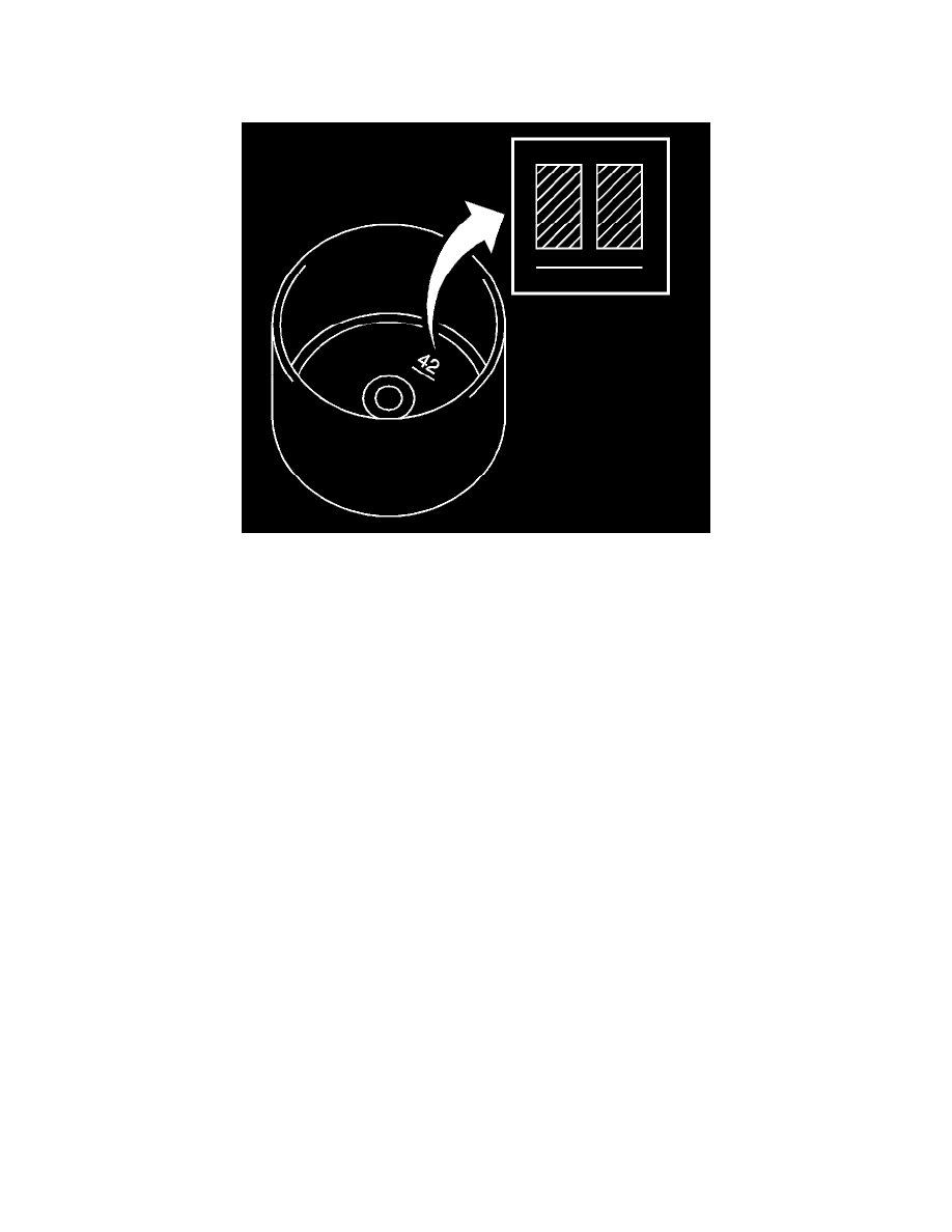
4. Closest new lifter equals 5.420 mm (0.2134 in.) - Select No. 42 lifter.
Note:
*
Lifters are available in 35 sizes in increments of 0.020 mm (0.0008 in), from 5.060-5.740 mm (0.1992-0.2260 in).
*
The identification number inside the valve lifters shows the value to 2 decimal places. The illustration shows 5.420 mm (0.2134 in).
6. Select a new lifter with a thickness as close as possible to the calculated values. Refer to Engine Mechanical Specifications (See:
Specifications/Service Limits & General Specifications) for the Selective Lifter Thickness Table.
7. Standard intake valve clearance (cold): 0.19-0.29 mm (0.007-0.011 in).
EXAMPLE: The 5.250 mm (0.2067 in) lifter is installed, and the measured clearance is 0.400 mm (0.0157 in). Replace the 5.250 mm (0.2067 in)
lifter with a new No. 42 lifter.
8. Standard exhaust valve clearance (cold): 0.38-0.48 mm (0.015-0.019 in).
EXAMPLE: he 5.340 mm (0.2102 in) lifter is installed, and the measured clearance is 0.510 mm (0.020 in). Replace the 5.340 mm (0.2102 in.)
lifter with a new No. 42 lifter.
9. Install the selected valve lifter.
10. Install the intake camshaft. Refer to Intake Camshaft and Valve Lifter Replacement (See: Camshaft, Lifters and Push Rods/Camshaft/Service and
Repair/Intake Camshaft and Valve Lifter Replacement).
11. Install the exhaust camshaft. Refer to Exhaust Camshaft and Valve Lifter Replacement (See: Camshaft, Lifters and Push Rods/Camshaft/Service
and Repair/Exhaust Camshaft and Valve Lifter Replacement).
12. Install the No. 1 chain tensioner.
13. Install the cylinder head cover. Refer to Camshaft Cover Replacement (See: Cylinder Head Assembly/Valve Cover/Service and Repair).
14. Install the spark plug. Refer to Spark Plug Replacement (See: Spark Plug/Service and Repair).
15. Install the ignition coil assembly. Refer to Ignition Coil Replacement (See: Powertrain Management/Ignition System/Ignition Coil/Service and
Repair).
16. Inspect for oil leak.
17. Inspect the ignition timing.
18. Install the engine cover. Refer to Engine Cover Replacement (See: Service and Repair/Removal and Replacement/Engine Cover Replacement).
19. Install the engine under right cover.