
Vibe FWD L4-2.4L (2009)
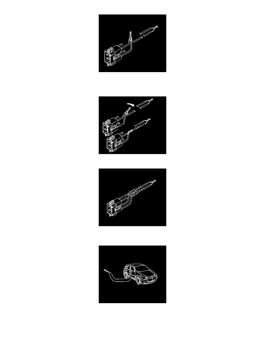
60. Twist together 2 connector wire leads (the low circuits from both stages of the steering wheel module) to one sets of deployment wires. Refer to
Component Connector End Views (See: Diagrams/Connector Views) in order to determine the correct circuits.
61. Inspect that the 3 wire connection is secure.
62. Bend flat the twisted connection.
63. Secure and insulate the 3 wire connection to deployment harness using electrical tape.
64. Connect the deployment harness to the IPM inline connector.
65. Route the deployment harness out of the passenger side of the vehicle.