
Vibe FWD L4-2.4L (2009)
Caution: Refer to Fastener Caution (See: Service Precautions/Vehicle Damage Warnings/Fastener Caution).
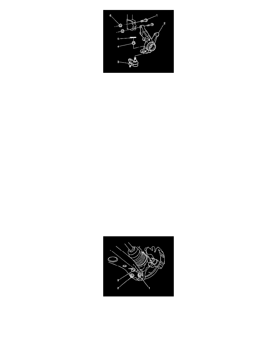
Note: Do not loosen the nut in order to insert the cotter pin.
1. Install the ball joint (3) and the nut (4) to the steering knuckle (2). If the vehicle has the 1.8L VIN 8 engine, tighten the nut to 103 Nm (76 lb ft). If
the vehicle has the 2.4L VIN 0 engine, tighten the nut to 123 Nm (91 lb ft). With either engine, tighten the nut up to 1/6 additional turn in order to
insert the cotter pin.
2. Install a NEW cotter pin (5) to the ball joint stud. Bend the cotter pin ends in order to retain the nut.
3. Install the front wheel bearing and the disc brake shield to the steering knuckle. Refer to Front Wheel Hub, Bearing, and Seal Replacement (1.8L
Engine) (See: Suspension/Wheel Bearing/Service and Repair/Front Wheel Hub, Bearing, and Seal Replacement)Front Wheel Hub, Bearing, and
Seal Replacement (2.4L Engine) (See: Suspension/Wheel Bearing/Service and Repair/Front Wheel Hub, Bearing, and Seal Replacement).
Note: Do not tighten the nuts or the bolts yet.
4. Install the following components to the lower side of the strut assembly:
*
The steering knuckle
*
The 2 bolts (1)
*
The 2 nuts (6)
Note: Do not loosen the nut in order to insert the cotter pin.
5. Install the outer tie rod end and the nut to the steering knuckle. Tighten the nut to 49 Nm (36 lb ft). Tighten the nut up to 1/6 additional turn in
order to insert the cotter pin.
6. Install a NEW cotter pin to the outer tie rod end ball joint stud. Bend the cotter pin ends in order to retain the nut.
7. Install the front brake rotor. Refer to Front Brake Rotor Replacement (See: Brakes and Traction Control/Disc Brake System/Brake
Rotor/Disc/Service and Repair/Removal and Replacement/Front Brake Rotor Replacement).
8. Install a NEW drive shaft nut while an assistant applies the brakes. Tighten the nut to 216 Nm (159 lb ft).
9. Stake the drive shaft nut into the slot on the wheel drive shaft.
10. Remove the wire supporting the front wheel drive shaft.
11. Install the bolt (3) and the 2 nuts (1, 2) to the control arm. Tighten the bolt and the 2 nuts to 89 Nm (66 lb ft).
12. Tighten the nuts and the bolts that retain the knuckle to the strut assembly to 240 Nm (177 lb ft).
13. Install the ABS wheel speed sensor to the knuckle. Refer to Front Wheel Speed Sensor Replacement (See: Brakes and Traction Control/Antilock
Brakes / Traction Control Systems/Wheel Speed Sensor/Service and Repair).
14. Install the tire and wheel assembly. Refer to Tire and Wheel Removal and Installation (See: Wheels and Tires/Service and Repair).
15. Lower the vehicle.
16. Measure the front wheel alignment. Adjust as necessary. Refer to Wheel Alignment Measurement (See: Alignment/Service and Repair/Wheel
Alignment Measurement).