
911 Carrera 4 Cabriolet AWD F6-3600cc 3.6L SOHC (1990)
Alignment: Service and Repair
Alignment Note
Accurate front axle height adjustment is critical to toe-in, camber, and caster adjustments. Ensure tire pressures are at their specified values,
fuel tank is full, spare tire is in place, and a weight approximately the same as the driver, positioned on the driver's seat.
Camber
1.
Loosen retaining bolt nuts and eccentric bolt nuts at the rear axle flange.
2.
Rotate tracking and camber eccentrics to adjust.
3.
Tighten eccentric and retaining nuts.
Axle Height
1.
Depress front of vehicle several times and allow to rebound to proper height.
2.
Measure distance between level floor or ramp to center of wheel hub (dimension a).
3.
Value a minus 4.25 inches should equal value b. Value b equals the distance between the torsion bar center and the level surface on which the
vehicle is positioned.
4.
Remove torsion bar dust cover at adjusting lever. Use torsion bar centering mark as a reference mark.
5.
Loosen or tighten torsion bar adjusting bolt until value b is obtained at the torsion bar center.
6.
Depress front of vehicle and allow to rebound to proper height. Recheck vehicle height. The allowable difference in height between left and
right sides of the vehicle is .2 inch (5 mm).
Camber & Caster
1.
Pull front luggage compartment carpeting away from shock towers.
2.
Remove sealing compound from pressure plates and movable dish ring.
3.
Mark position of single and double hole plates and screws.
4.
Position shock absorber strut supporting bearing to adjust caster or camber.
5.
Torque bolts to 33.8 ft. lbs. and seal plates with a suitable sealing compound.
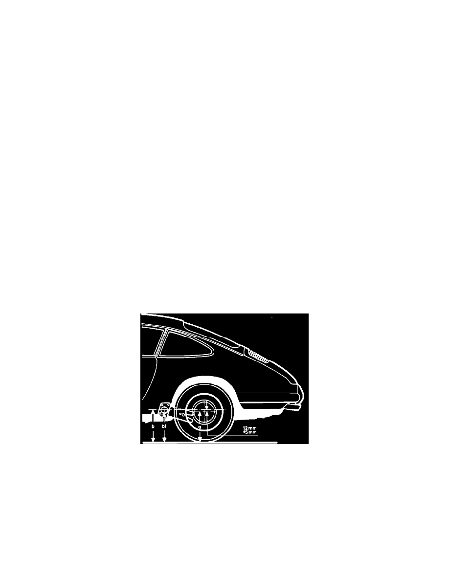
Rear Axle Height
Fig. 4 Rear Axle Height Adjustment
1.
Depress rear of vehicle several times and allow body to rebound.
2.
Measure vertical distance between rear wheel center and level section of alignment ramp or level floor (distance a), Fig. 4.
3.
Value of a plus .4724 inch (12 mm) equals value b. The value b cannot be measured since the torsion bar is off center.
4.
Value b less bushing cover radius (1/2 diameter) equals value b1.
5.
Measure height of vehicle (value b1), Fig. 4.The actual value b1 should not differ from the calculated b1 by more than .1968 inch (5 mm). The
height difference between right and left sides of the vehicle should be no more than .3145 inch (8 mm). For example: value a, 12.40 inches (315
mm) + .47inch (12 mm) = 12.87inches (327 mm) - bushing cover radius, 1.18 inches (30 mm) = 11.69 inches (297 mm) = b1 or vehicle height)
6.
If proper suspension height cannot be achieved, proceed as follows:
a. Check adjustment of front suspension and correct if necessary.
b. Check rear torsion bar adjustment and correct if necessary.