
928 S V8-4957cc 5.0L (1985)
Engine Control Module: Connector Views
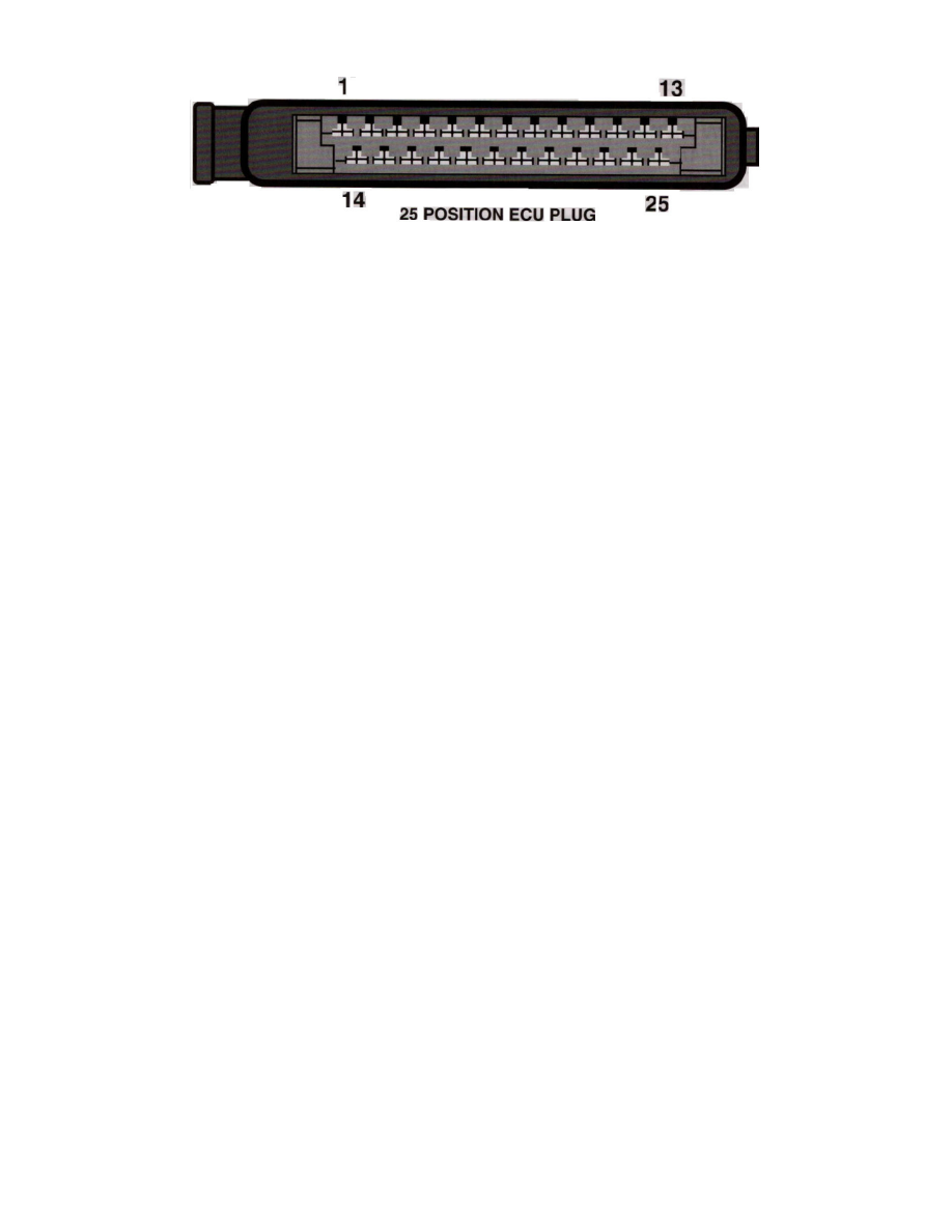
25 Position ECU Plug
Pin Layout
System
LH-Jetronic
Location
- Kick panel passenger side
Terminal ID
1 - Trigger from EZF ECU pin 16 (Ppl/Gry)
2 - Coolant Temperature Sensor (Grn)
3 - Idle Switch (Wht)
4 - N/A
5 - Ground (Brn)
6 - Air Mass Meter Ground (Gry/Blk)
7 - Air Mass Meter Load (Gry/Grn)
8 - Air Mass Meter Burn-off (Blk/Grn)
9 - Main Relay Supply (Blk/Wht)
10 - ISC Valve Control (Red/Blu)
11 - Ground (Brn)
12 - Full Load Throttle Switch (Wht/Red)
13 - Injector Driver Output (Brn/Red)
14 - Air Mass Meter CO Adjustment (Gry/Red)
15 - N/A
16 - Air Conditioning (Grn/Red)
17 - Fuel Pump Relay Control (Brn/Red)
18 - EZF Relay Power (Blk)
19 - Low Octane Adjust* (Brn)
20 - Oxygen Sensor Input (Grn)
21 - Main Relay Control (Brn/Wht)
22 - Integrator Output (Pnk)
23 - ISC Valve Control (Grn/Red)
24 - N/A
25 - Ground (Brn)