
928 S4 V8-4957cc 5.0L (1987)
Alignment: Service and Repair
Front Suspension
Accurate front axle height adjustment is critical to toe-in, camber, and caster adjustments. Ensure tire pressures are at their specified values,
fuel tank is full, spare tire is in place, and a weight approximately the same as the driver, positioned on the driver's seat.
AXLE HEIGHT, ADJUST
Fig. 1 Front suspension height check point.
928 Less Adjustable Spring Struts
1.
Measure distance from floor to milled surface of lower control arm mount, Fig. 1. Distance should be 6.6929-7.4803 inches (170-190 mm) with a
maximum left to right difference of .3937 inch (10 mm).
2.
Slight adjustment can be made by the installation of spacers underneath the lower spring retainer. Each spacer will increase axle height
approximately .3937 inch (10 mm). Never use more than two spacers per spring strut.
3.
If axle height can not be adjusted to specifications with spacers, front springs must be replaced. Springs which have approximately 45 lbs. more
spring force for the same test strength will increase front axle height by approximately .1969-.5906 inch (5-15 mm).
928 W/Adjustable Spring Struts
1.
Measure distance from floor to milled surface of lower control arm mount, Fig. 1. Distance should be 6.6929-7.4803 inches (170-190 mm) with a
maximum left to right difference of .3937 inch (10 mm).
2.
To adjust axle height, turn adjusting nuts at bottom of spring on strut. With vehicle resting on ground, turn wheels against lock accordingly to gain
access to adjusting nuts. Turn nuts clockwise to increase height or counterclockwise to decrease height. The adjusting range for lowering the
vehicle is limited by a stop for the adjusting nut on vehicles with Bilstein spring struts. On vehicles with Boge spring struts, the lowest
position has been reached when the adjusting nut turns easily.
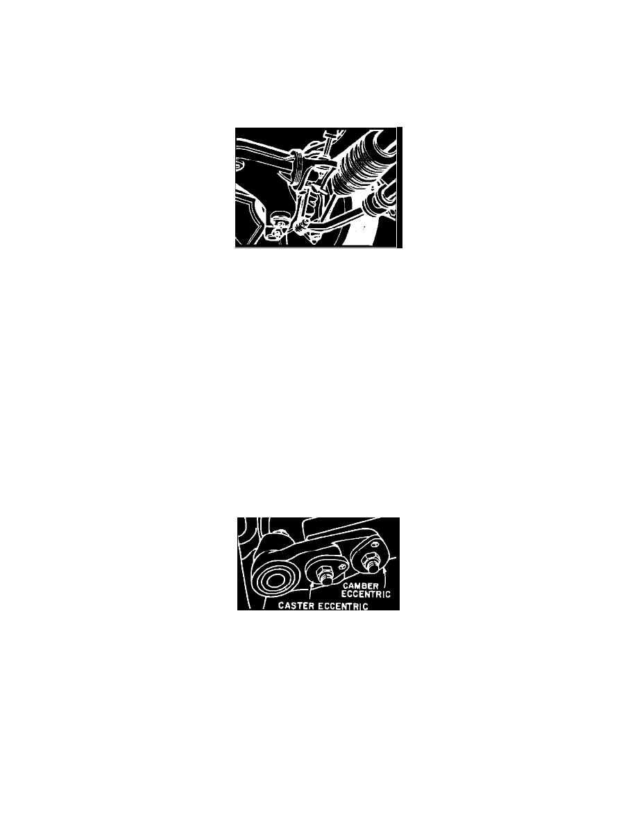
CAMBER & CASTER, ADJUST
Fig. 3 Front caster & camber adjustment eccentrics.
On vehicles w/aluminum joint carriers, adjust caster and camber by rotating two eccentrics on lower control arm, Fig. 3.
Caster and camber on vehicles w/steel joint carrier is adjusted in same way, but location of caster and camber eccentrics are opposite those shown in
Fig. 3.
On vehicles w/aluminum joint carrier, always turn caster eccentric from small caster in direction of large caster. When caster is excessive, first turn the
eccentric back completely and then adjust to correct value. If specified caster cannot be obtained, opposite side may be corrected to a value of up to 4°
30'.