
944 L4-2681cc 2.7L (1989)
Control Assembly: Description and Operation
Air Conditioning System
AIR-CONDITIONING SYSTEM FROM 85/2
Starting with the 85/2 model, the air-conditioning system was revised. The evaporator is located together with the heat exchanger in one housing.
Temperature control is automatic. The flaps, which are actuated by electric control motors, are regulated via 3 temperature sensors. The preselected
temperature is maintained over the entire period of travel.
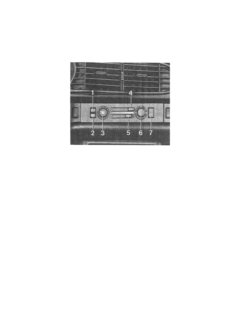
The electronics which process the signals are located in the control switch.
1 Ventilation switch
2 Defrost switch
3 Outside air blower switch
4 Defrost slide switch
5 Footwell slide switch
6 Temperature setting switch
7 A/C switch
When switch 1 is pressed, the outside-air openings are closed and conversion is made to air- circulation.
When switch 2 is pressed, irrespective of the sliding switch position (4 and 5), the footwell flap is closed and the defrost flap opened. At the same time,
the heater is turned all the way up, the outside air blower switched to level 4, and the A/C compressor switched on.
The outside air switch 3 has 5 positions. In position 0, the outside air blower starts upon ignition at the lowest speed.
Slide switch 4
Left stop - defrost flap closed
Right stop - defrost flap open
Slide switch 5
Left stop - footwell flap closed
Right stop - footwell flap open
Temperature setting switch 6
Left stop - maximum cooling
Right stop - maximum heating
When switch 7 is pressed, the A/C compressor is switched on.