
968 Coupe L4-2990cc 3.0L DOHC (1992)
Air Flow Meter/Sensor: Description and Operation
DESCRIPTION
The air flow sensor, a heated wire type sensor located between the air cleaner and the throttle valve housing, is used for the measurement of intake air
for the Digital Motor Electronics (DME) unit.
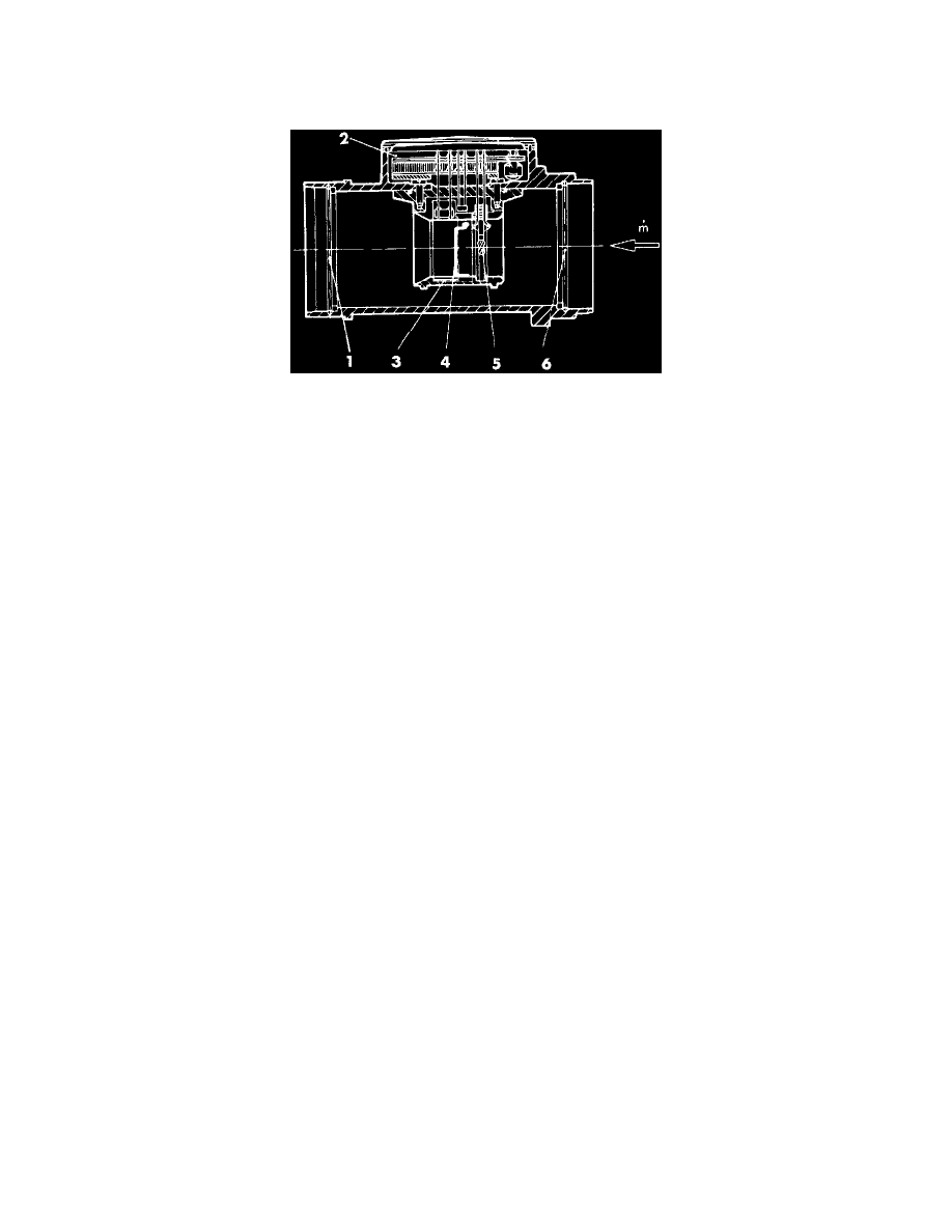
ARRANGEMENT OF AIR FLOW SENSOR
1 -
Protective grid
2 - Regulator housing
3 - Measuring resistor
4 - Heated wire
5 - Intake air compensation resistor
6 - Protective grid
OPERATION
Circuit
The compensation resistor RK, heated wire RH and measuring resistor RM are connected up to the trimming resistor R2 to form a bridge circuit.
The bridge is trimmed by resistor R2 in such a way that the heated wire's temperature-dependent resistor adopts a value which represents a
temperature difference of 155° C to the intake-air temperature. This temperature difference is kept constant.
Functioning at constant air throughput and variable intake-air temperature:
If the intake-air temperature rises, the resistance RK and the voltage drop at RK + R1 increase. This change causes the current through RH to increase.
As a result, the temperature of the heated wire is raised until its difference to the intake-air temperature is once again 155° C. The resulting
simultaneous change in voltage at RM constitutes the signal for the control unit. The change in air density is therefore detected via its temperature.
Functioning at constant intake-air temperature and variable air throughput:
If the air throughput rises, the heated wire cools down more rapidly. In order to maintain the temperature difference of 155° C, the heating current has
to be increased. This change in the current causes the voltage at resistor RM to change; this change is registered by the control unit.