
18I/Sportwagon L4-2165cc 2.2L (1985)
Control Module: Testing and Inspection
The following procedures can be performed using standard shop equipment. However, further testing of electronic control components
requires the use of diagnostic tester B.Vi.958 (early models), MS 1700 (late models) or a suitable equivalent.
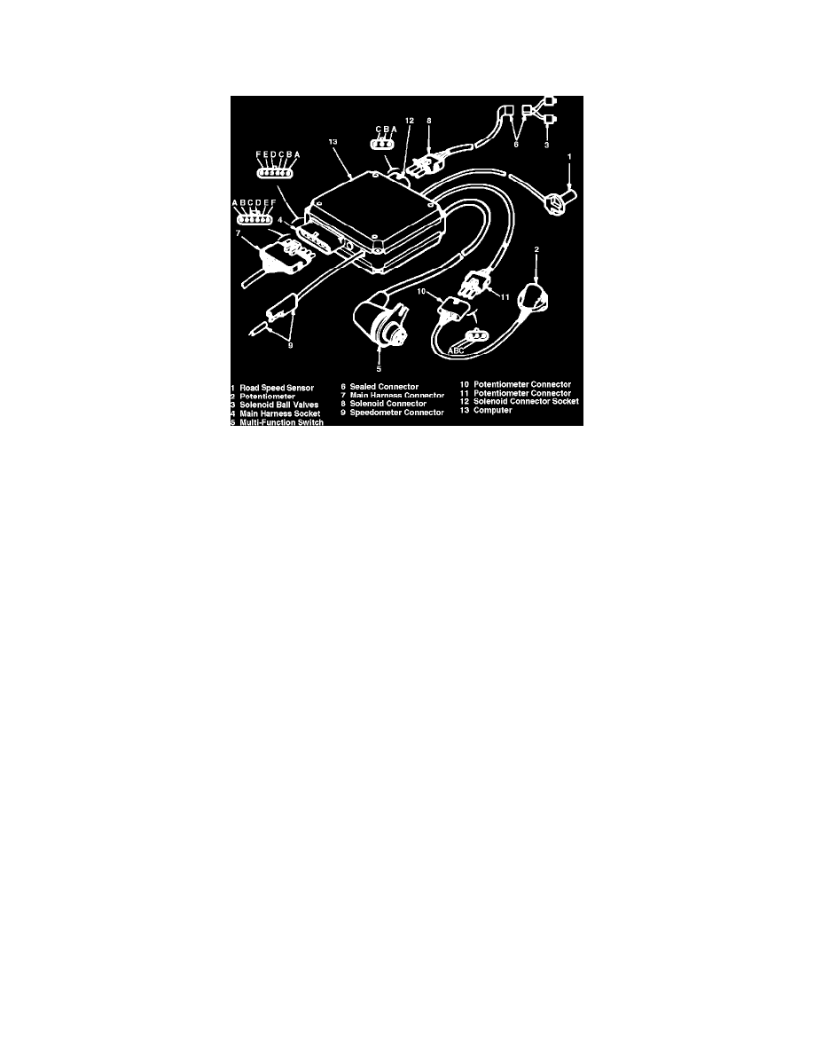
Fig. 3 Electronic control component identification
1.
Disconnect main harness connector from computer, Fig. 3.
2.
Connect ohmmeter between terminal B on connector and ground.
3.
If reading is not 1-7 ohms, check and repair back-up lamp circuit.
4.
Connect voltmeter between connector terminal A and ground.
5.
If reading is not 10-14 volts with ignition off, check and repair back-up lamp feed circuit.
6.
Connect ohmmeter between connector terminal E and ground.
7.
If reading is not 0 ohms with ignition off, repair system ground circuit.
8.
Connect voltmeter between connector terminal F and ground.
9.
If reading is not 10-14 volts with ignition on, repair computer feed circuit.
10.
Connect voltmeter between connector terminal C and ground and operate starter.
11.
If reading is not 10-14 volts, check and repair starter circuit.