
Alliance/Encore L4-1397cc 1.4L (1984)
Throttle Position Sensor: Testing and Inspection
The following procedures can be performed using standard shop equipment. However, further testing of electronic control components
requires the use of diagnostic tester B.Vi.958 (early models), MS 1700 (late models) or a suitable equivalent.
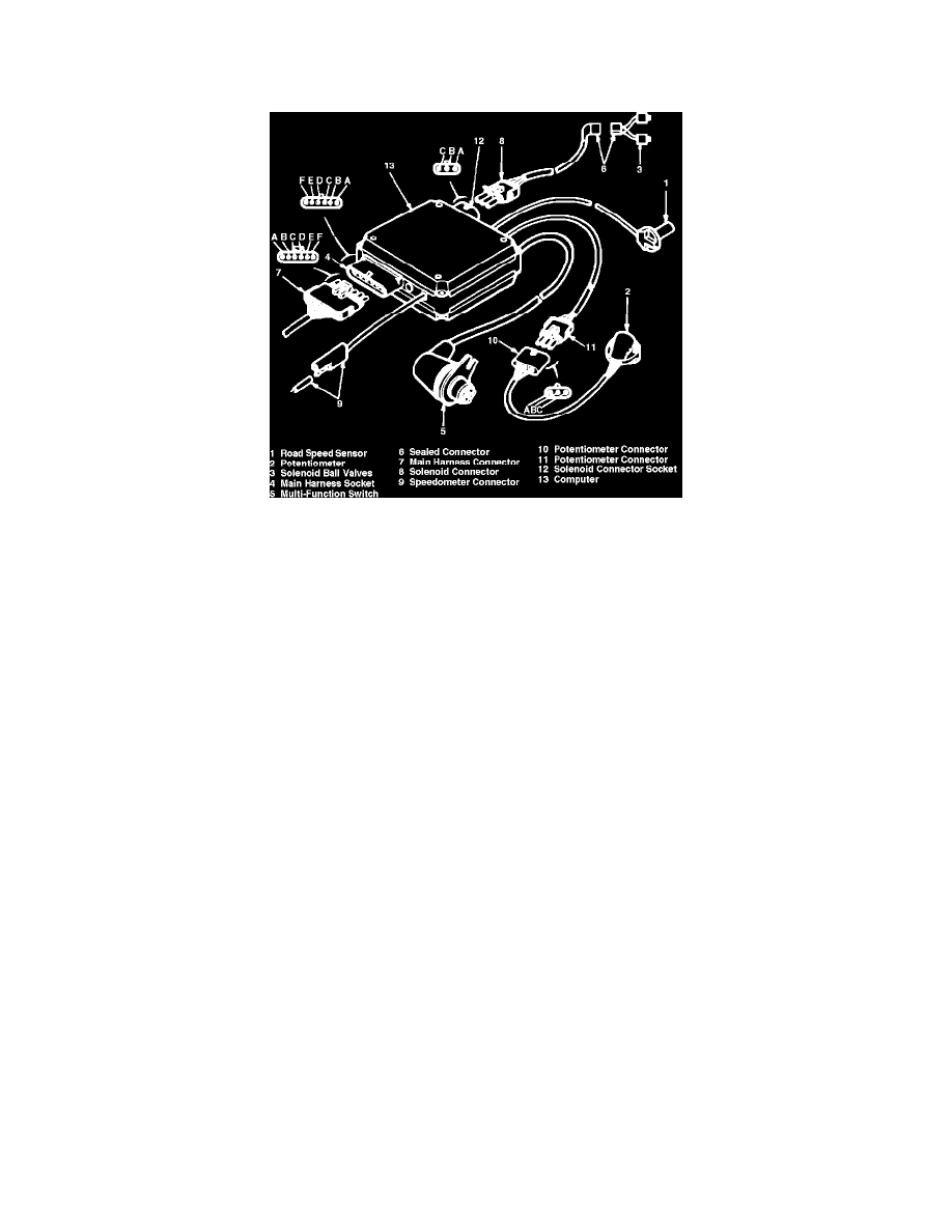
Fig. 3 Electronic control component identification
Potentiometer Input Voltage Check
1.
Separate potentiometer connectors, Fig. 3.
2.
Connect voltmeter between terminal B on computer connector (K) and ground, then turn on ignition.
3.
If reading is not 3.8-4.8 volts, check computer feed circuit as outlined in ``Main Harness Check.''
4.
If computer feed is satisfactory, but potentiometer input voltage is not within specifications, computer is defective.
Potentiometer Check
1.
Separate potentiometer connectors, Fig. 3.
2.
Connect ohmmeter between terminals B and C on potentiometer connector (J). Reading should be approximately 4000 ohms.
3.
Connect ohmmeter between terminals A and B of potentiometer connector (J). Reading should be approximately 2500 ohms with throttle closed.
4.
Slowly open throttle while observing ohmmeter. Meter reading should increase, but should not reach infinite resistance.
5.
If readings are not as outlined, throttle position sensor is improperly adjusted or defective.