
9-2X F4-2.5L (2006)
Turn Signals: Diagnostic Aids
Basic Inspection
Basic Inspection
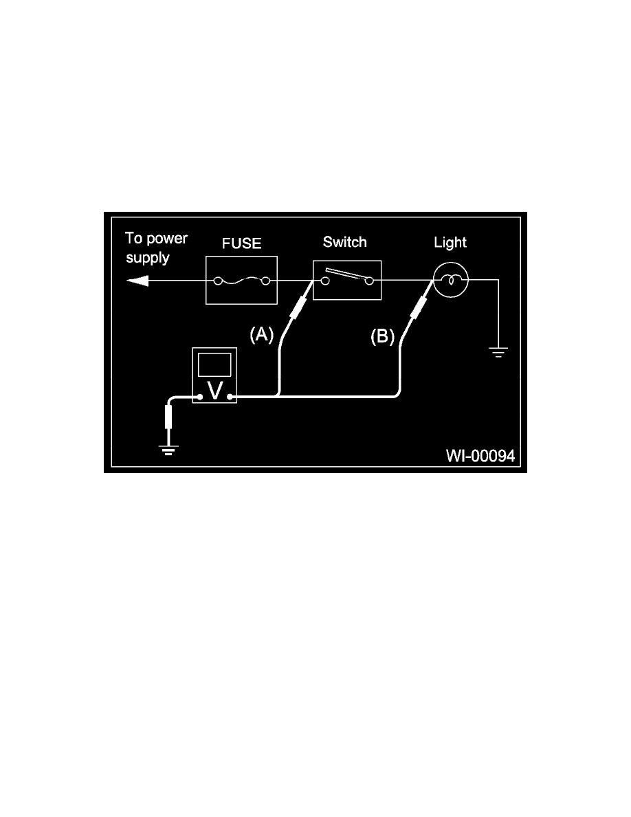
VOLTAGE MEASUREMENT
Using a voltmeter, connect the negative lead to a good ground point or negative battery terminal and the positive lead to the connector or component
terminal.
Contact the positive lead of the voltmeter on connector (A). The voltmeter will indicate a voltage.
Shift the positive lead to connector (B). The voltmeter will indicate no voltage.
With the test set-up held as it is, turn the switch ON. The voltmeter will indicate a voltage and, at the same time, the light will come on.
The circuit is in good order. If a problem such as a light failing to illuminate occurs, use the procedures outlined above to track down malfunction.
CIRCUIT CONTINUITY CHECKS
Disconnect the battery terminal or connector so there is no voltage between check points.
Contact the two leads of an ohmmeter to each of the check points.
If the circuit has diodes, reverse the two leads and check again.
Use an ohmmeter to check for the diode continuity. When contacting the negative lead to diode positive side and positive lead to negative side, there
should be continuity.
When contacting the two leads in reverse, there should be no continuity.