
9-7X L6-4.2L (2008)
Seat Heater: Symptom Related Diagnostic Procedures
Front Heated Seat Malfunction
Front Heated Seat Malfunction
Diagnostic Instructions
*
Perform the Diagnostic System Check - Vehicle (See: Testing and Inspection/Initial Inspection and Diagnostic Overview/Diagnostic System
Check - Vehicle) prior to using this diagnostic procedure.
*
Review Strategy Based Diagnosis (See: Testing and Inspection/Initial Inspection and Diagnostic Overview/Strategy Based Diagnosis) for an
overview of the diagnostic approach.
*
Diagnostic Procedure Instructions (See: Testing and Inspection/Initial Inspection and Diagnostic Overview/Diagnostic Procedure Instructions)
provides an overview of each diagnostic category.
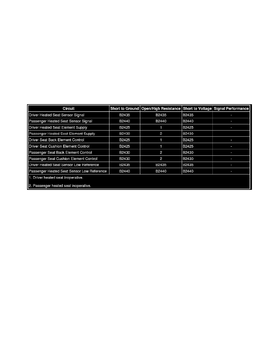
Diagnostic Fault Information
Circuit/System Description
The memory seat module (MSM) controls the voltage supply and the ground circuits to the seat heater elements. When a heated seat function is
commanded active, the MSM will switch battery voltage to the heater element supply circuits, and ground is provided through low side drive control
circuits. During heated seat operation both the seat back and cushion heater elements are supplied battery voltage. The MSM grounds the appropriate
control circuits for back only or back and cushion heating modes, and opens or closes the active control circuits as necessary in order to maintain the
desired seat temperature. The MSM relies on inputs from thermistors located in the driver and passenger seat backs to control heated seat temperatures.
The thermistors are 2 wire sensors supplied with a 5-volt referenced signal circuit and low reference circuit from the MSM. Resistance through the
thermistors varies with temperature causing the heated seat sensor signal circuit voltage levels to decrease as the seat back temperatures rise
Reference Information
Schematic Reference
Heated/Cooled Seat Schematics (See: Diagrams/Electrical Diagrams)
Connector End View Reference
Component Connector End Views (See: Diagrams/Connector Views/Component Connector End Views)
Description and Operation
Heated Seats Description and Operation (See: Description and Operation)
Electrical Information Reference
*
Circuit Testing (See: Testing and Inspection/Component Tests and General Diagnostics/Circuit Testing/Circuit Testing)
*
Connector Repairs (See: Testing and Inspection/Component Tests and General Diagnostics/Connector Repairs/Connector Repairs)
*
Testing for Intermittent Conditions and Poor Connections (See: Testing and Inspection/Component Tests and General Diagnostics/Circuit
Testing/Testing for Intermittent Conditions and Poor Connections)
*
Wiring Repairs (See: Testing and Inspection/Component Tests and General Diagnostics/Wiring Repairs/Wiring Repairs)
Scan Tool Reference