
9-7X L6-4.2L (2008)
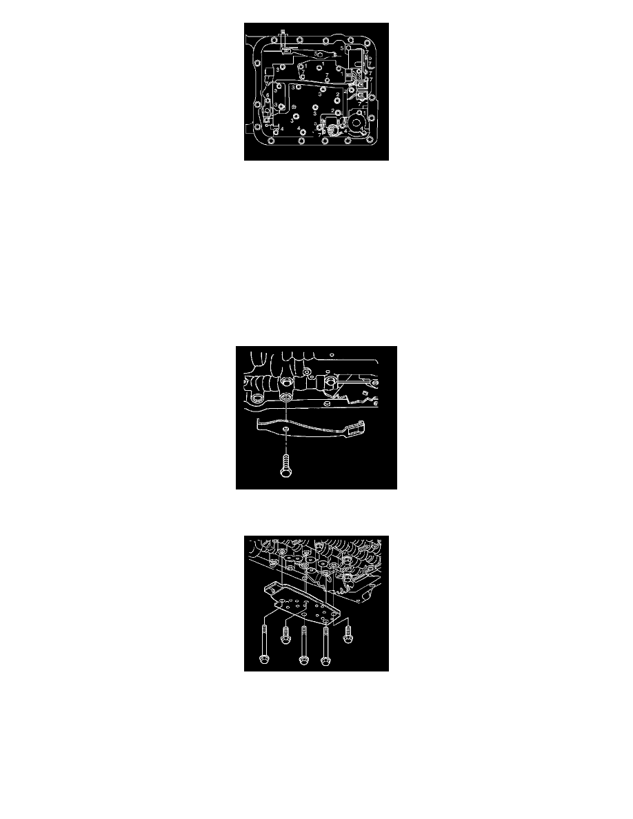
Important: When installing bolts throughout this procedure, be sure to use the correct bolt size and length in the correct location as
specified.
5. Do not install the transmission fluid indicator stop bracket and bolt at this time.
Install but do not tighten the control valve body bolts which retain only the valve body directly.
Each numbered bolt location corresponds to a specific bolt size and length, as indicated by the following:
*
M6 X 1.0 X 65.0 (1)
*
M6 X 1.0 X 54.4 (2)
*
M6 X 1.0 X 47.5 (3)
*
M6 X 1.0 X 35.0 (4)
*
M8 X 1.0 X 20.0 (5)
*
M6 X 1.0 X 12.0 (6)
*
M6 X 1.0 X 18.0 (7)
6. Install the manual detent spring.
7. Install but do not tighten the manual detent spring retaining bolt.
8. Install the transmission fluid pressure switch.
9. Install but do not tighten the control valve body bolts which retain the transmission fluid pressure switch to the control valve body.
Notice: Refer to Fastener Notice.
Notice: Torque valve body bolts in a spiral pattern starting from the center. If the bolts are torqued at random, valve bores may be
distorted and inhibit valve operation.