
9-7X V8-5.3L (2005)
Pump Cover 3 (Pre-ISS models): Late in the 2005 model year, the pump cover casting was modified in order to incorporate the input speed sensor (ISS)
connector. This modification will remove metal directly below the pressure regulator valve and reverse boost valve bore and extend a cast wall inward.
This wall establishes the mounting point for the ISS connector. The casting change will also create a mounting surface for the ISS assembly. The ISS
location places the assembly in position to target the rotor teeth on the input turbine shaft. Because of this mounting location, the internal TCC release oil
pump passage had to be modified. This affected the stator shaft and the stator shaft bushing. A new stator shaft and bushing are used to relocates the oil
passages in the pump cover. The turbine shaft for this pump has relocated oil seal ring grooves that correlate with the new stator shaft and stator shaft
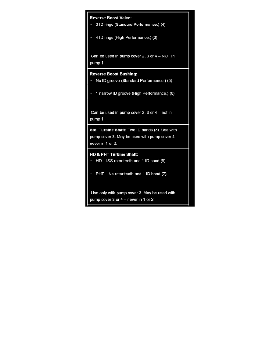
bushing. The turbine shaft oil grooves were moved to create an area to manufacture the ISS rotor teeth. Turbine shafts with relocated oil grooves can be
identified as shown in the illustration as well as the noticeable large land area just ahead of the first oil seal ring groove. Some pre-ISS models may have
ISS rotor teeth on the turbine shaft and some may not. This was a manufacturing option. Either way, with or without ISS rotor teeth, these turbine shafts
cannot be installed into early design pump covers due to the relocation of the oil pump TCC oil circuits and the turbine shaft oil seal ring groove
locations.