
9-7X V8-6.0L (2008)
Ignition Switch Lock Cylinder: Description and Operation
KEY AND LOCK CYLINDER CODING
KEY IDENTIFICATION AND USAGE
The lock cylinder keyway is designed so that other model keys will not enter a current model lock cylinder. A single key is used for all locks on the
vehicle.
The key identification is obtained from the four-character key code stamped on the knockout portion of the key head. Knock the plugs out of the key
head after code numbers have been recorded. The code list, available to owners of key cutting equipment from equipment suppliers, determines the
lock combinations from the code numbers.
CUTTING KEYS
After the code has been determined from the code list or the key code diagram, perform the following steps:
1. Cut a blank key to the proper level of each of the tumbler positions.
2. Inspect the key operation in the lock cylinder.
REPLACEMENT LOCK CYLINDERS
New lock cylinders (except ignition lock cylinders) are available from the service parts warehouse with new lock cylinder locking bars. The tumblers
are also available and must be assembled into the cylinder as recommended. For additional information, refer to the following.
LOCK CYLINDER TUMBLER OPERATION
All lock tumblers are shaped alike with the exception of the notched position on one side. As the key is inserted into the lock cylinder, the tumblers are
lowered to the correct height so that notches on each tumbler are at the same level. When the notches on all 6 tumblers line up, 2 small springs push
the side bar into the notches, allowing the cylinder to turn in the cylinder bore. Five types of tumblers are used in making the lock combinations, and
each is coded and stamped with a number between 1 and 5.
ASSEMBLING AND CODING IGNITION LOCK CYLINDERS
TOOLS REQUIRED
J 41340 Ignition Lock Holding Fixture
1. Determine the tumbler numbers/arrangement:
1. Place the tip of the key directly over the tip of the illustrated key.
2. Inspect that the diagram outlines the key.
3. Starting with position 1 (open end of cylinder), find and record the lowest level (tumbler number) that is visible.
4. Repeat the previous step for positions 2-10.
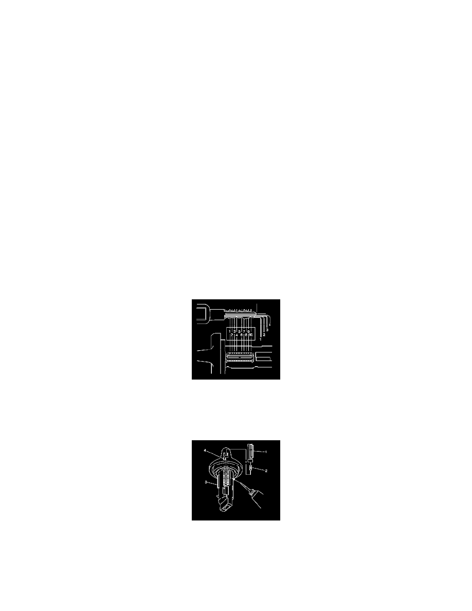
2. Starting with position 1, insert the tumblers (4) into their corresponding slots in the coded order.
3. Using your fingers, pull out the side bar (3) until the tumblers fall completely into place.
4. Insert one tumbler spring (2) above each tumbler (4).
5. Lubricate the tumblers using Superlube(R) GM P/N 12346241 or equivalent.
6. Insert the spring retainer (1) prongs into the slots at the end of each cylinder.