
9-7X V8-6.0L (2008)
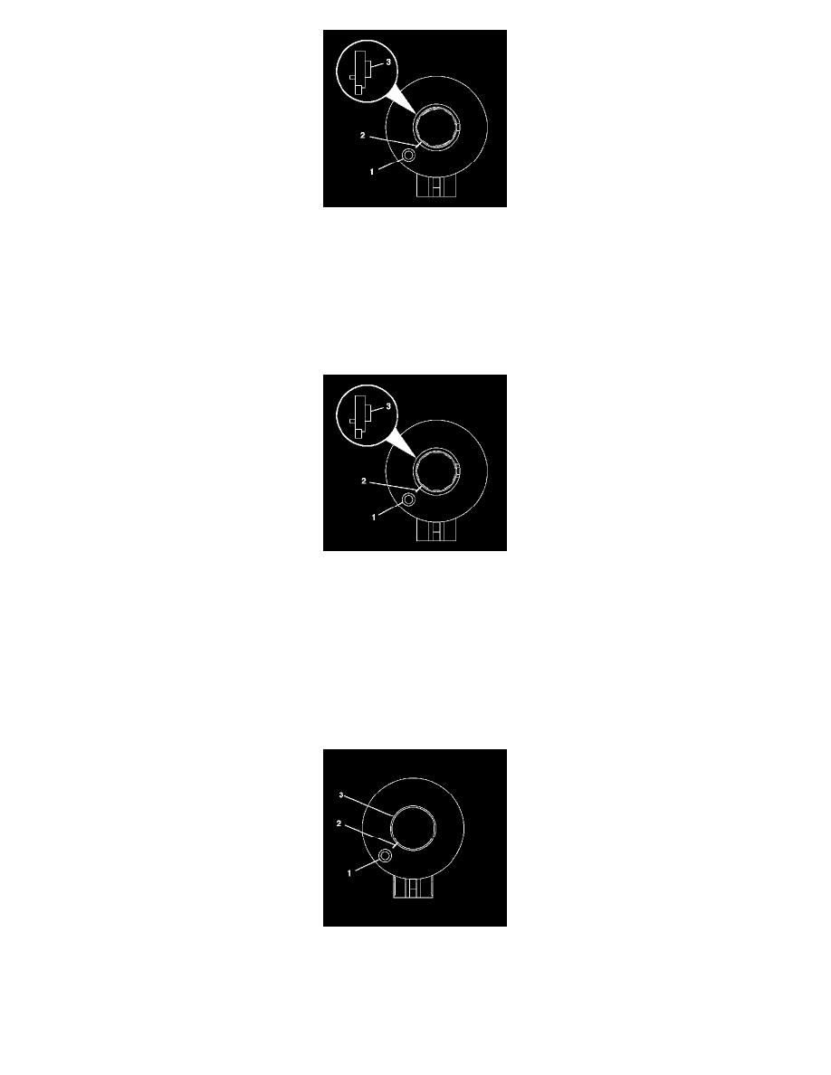
11. From the technicians point of view, the FRONT of the sensor will have:
*
raised rotor flange cuff (3)
*
alignment mark (2) on rotor flange cuff (3) for installation
*
pin hole (1) for centering pin (note location of pin hole)
12. Remove the connector from the sensor.
13. Remove the sensor from the adapter and bearing assembly.
14. To install the sensor, proceed to step 9 in the installation section.
15. From the technicians point of view, the FRONT of the sensor will have:
*
raised rotor flange cuff (3)
*
alignment mark (2) on rotor flange cuff (3) for installation
*
pin hole (1) for centering pin (note location of pin hole)
*
sensor clip in FRONT of the sensor
16. Remove the connector from the sensor.
17. Remove the sensor clip from the sensor.
18. Remove the sensor from the adapter and bearing assembly.
19. To install the sensor, proceed to step 13 in the installation section.
20. From the technicians point of view, the FRONT of the sensor will have:
*
flush rotor flange cuff (3)
*
pin hole (1) for centering pin (note location of pin hole)
*
alignment mark (2) on flush rotor flange cuff (3) for installation