
9-7X V8-6.0L (2008)
Heated Glass Element: Symptom Related Diagnostic Procedures
Rear Window Defogger Malfunction
Diagnostic Instructions
*
Perform the Diagnostic System Check - Vehicle (See: Testing and Inspection/Initial Inspection and Diagnostic Overview/Diagnostic System
Check - Vehicle) prior to using this diagnostic procedure.
*
Review Strategy Based Diagnosis (See: Testing and Inspection/Initial Inspection and Diagnostic Overview/Strategy Based Diagnosis) for an
overview of the diagnostic approach.
*
Diagnostic Procedure Instructions (See: Testing and Inspection/Initial Inspection and Diagnostic Overview/Diagnostic Procedure Instructions)
provides an overview of each diagnostic category.
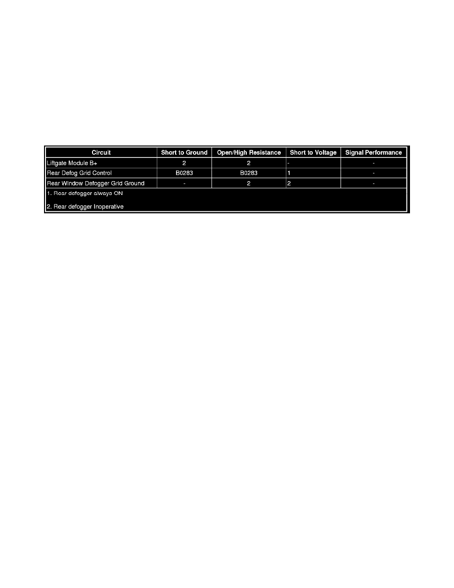
Diagnostic Fault Information
Circuit/System Description
The rear window defogger switch and indicator is an integral component of the HVAC control module. When the rear window defogger switch is
pressed, the HVAC control module responds by illuminating the defogger indicator and sending a GMLAN serial data message indicating a defog
request. This serial data message is received by the liftgate module (LGM). The LGM responds to the defog request by providing voltage to the rear
window defogger grid. Pressing the rear window defogger switch again will extinguish the indicator and send a GMLAN serial data message indicating
the defog deactivation command. The LGM responds by deactivating the defogger grid.
Reference Information
Schematic Reference
Defogger Schematics (See: Diagrams/Electrical Diagrams)
Connector End View Reference
Component Connector End Views (See: Diagrams/Connector Views/Component Connector End Views)
Description and Operation
Rear Window Defogger Description and Operation (See: Windows/Description and Operation/Rear Window Defogger Description and Operation)
Electrical Information Reference
*
Circuit Testing (See: Testing and Inspection/Component Tests and General Diagnostics/Circuit Testing/Circuit Testing)
*
Connector Repairs (See: Testing and Inspection/Component Tests and General Diagnostics/Connector Repairs/Connector Repairs)
*
Testing for Intermittent Conditions and Poor Connections (See: Testing and Inspection/Component Tests and General Diagnostics/Circuit
Testing/Testing for Intermittent Conditions and Poor Connections)
*
Wiring Repairs (See: Testing and Inspection/Component Tests and General Diagnostics/Wiring Repairs/Wiring Repairs)
Scan Tool Reference
Control Module References (See: Testing and Inspection/Programming and Relearning/Control Module References) for scan tool information
Circuit/System Verification
1. Ignition ON, observe the scan tool Rear Defrost Switch parameters while pressing the rear window defogger switch. The parameter should change
between On and Off.
‹› If the parameter does not change between commanded states, replace the HVAC control module.
2. Observe the operation of the rear window defogger indicator while pressing the rear window defogger switch. The indicator should turn ON or
OFF each time the rear window defogger switch is pressed.
‹› If the indicator does not turn ON or OFF with each switch press, replace the HVAC control module