
900 L4-1985cc 2.0L DOHC (1986)
Positive Crankcase Ventilation: Description and Operation
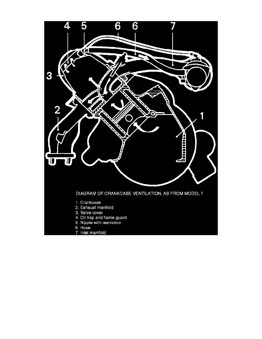
Fig.2 - Positive Crankcase Ventilation
PURPOSE
Crankcase emission controls prevent crankcase gases from escaping into the atmosphere. Instead, the gases are routed to the intake manifold where
they are ignited in the combustion process.
CONSTRUCTION
The crankcase ventilation system consists of a three-way nipple in the cylinder head cover, from which a small diameter hose runs to the intake
manifold and a larger diameter hose runs to the air cleaner, Fig. 1.
OPERATION
During normal operation, manifold vacuum is applied to the crankcase and blow-by gasses are drawn into the intake manifold through the smaller
hose.
When crankcase pressure is too low, air is drawn from the air cleaner through the nipple, then to intake manifold.
During full load operation, vacuum created in the air cleaner overcomes intake manifold vacuum and blow-by gasses are drawn into the intake
stream through the large diameter hose.