
900 L4-1985cc 2.0L DOHC Turbo EFI (1985)
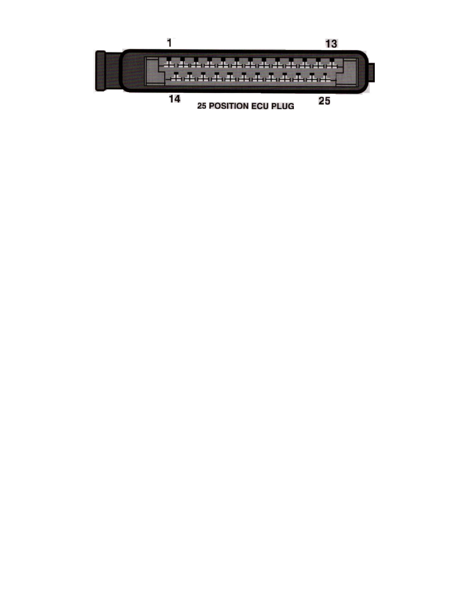
Engine Control Module: Connector Views
25 Position ECU Plug
Pin Layout
System
LH-Jetronic
Location
Passenger side kick panel
Terminal ID
1 - Coil (-) Trigger signal input (Blu)
2 - Coolant Temperature Sensor (Yel)
3 - Idle Switch (Gry)
4 - Start input (Org)
5 - Shield Ground 2 wires (Blk)
6 - Air Mass Meter Ground (Blu/Wht)
7 - Air Mass Meter Load (Org)
8 - Air Mass Meter Burn-off (Red/Wht)
9 - Main Relay Supply (Brn/Wht)
10 - ISC Valve Control (Blu/Wht)
11 - Ground (Blk)
12 - Full Load Throttle Switch (Grn/Red) (Blu)
13 - Injector Driver Output (Grn/Red)
14 - Air Mass Meter CO Adjustment (Wht)
15 - Ground (Blk)
16 - Air Conditioning Relay (Red/Wht)
17 - Fuel Pump Relay Control (Vio)
18 - Ignition Switch Power (Grn/Wht)
19 - Check Engine Light (Vio/Wht)
20 - Oxygen Sensor Input
21 - Main Relay Control (Yel/Wht)
22 - Integrator Output (Grn)
23 - ISC Valve Control (Yel/Red)
24 - Output to EZK ECU [No connection for systems not equipped.]
25 - Ground (Blk/Wht)