
900 L4-1985cc 2.0L DOHC Turbo EFI (1985)
Throttle Position Switch: Adjustments
E5 Checking and adjusting the throttle position sensor
Tools:
-
Multimeter
1 Unplug the control module connector and remove the cover.
2 Connect the multimeter between control module connector pins 3 (grey; GR) and 11 (black; SV). Check that the circuit is closed.
If there is a break in the circuit, check the grey lead from pin 3 of the connector to the throttle position sensor and the black lead from pin 11 of the
connector to ground, and the black/white lead from the throttle position sensor to ground.
3 Move the throttle butterfly and check the reading on the multimeter. If the sensor is in proper working order, the circuit should be broken the
moment the butterfly leaves its idling position. If it is not, adjust the position of the throttle butterfly (see M1, "Basic setting of throttle butterfly".)
Adjust the throttle position sensor by slackening the screws securing it to the throttle body. Turn the throttle position sensor until it abuts against
the integral idling position stop. Tighten the throttle position sensor retaining screws.
Check that the circuit between control module pins 3 (grey; GR) and 11 (black; SV) is broken when the throttle butterfly leaves its idling position
stop.
4 Connect the multimeter across pins 11 (black; SV) and 12 (green/red GN/RD). If the sensor is in proper working order, the circuit should be
closed when the throttle butterfly is turned through 720, i.e. approaching full throttle.
If the circuit is not closed, check the green/red (GN/RD) lead between pin 12 of the connector and pin 3 of the throttle position sensor, the black
lead between pin 11 of the control module and ground, and the black lead between pin 2 of the throttle position sensor and ground.
If the wiring is OK but the sensor is not working properly, fit a new throttle position sensor.
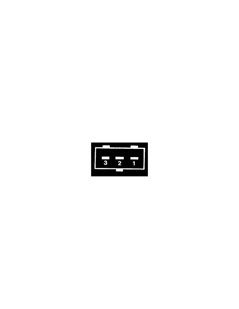
Throttle position sensor connections:
No.
Should be connected to:
3
Control module connector pin 12 (green/red; GN/RD)
2
Grounding point on engine (black/white; SV/VT)
1
Control module connector pin 3 (grey; GR)