
900 L4-1985cc 2.0L SOHC (1988)
Ignition Control Module: Description and Operation
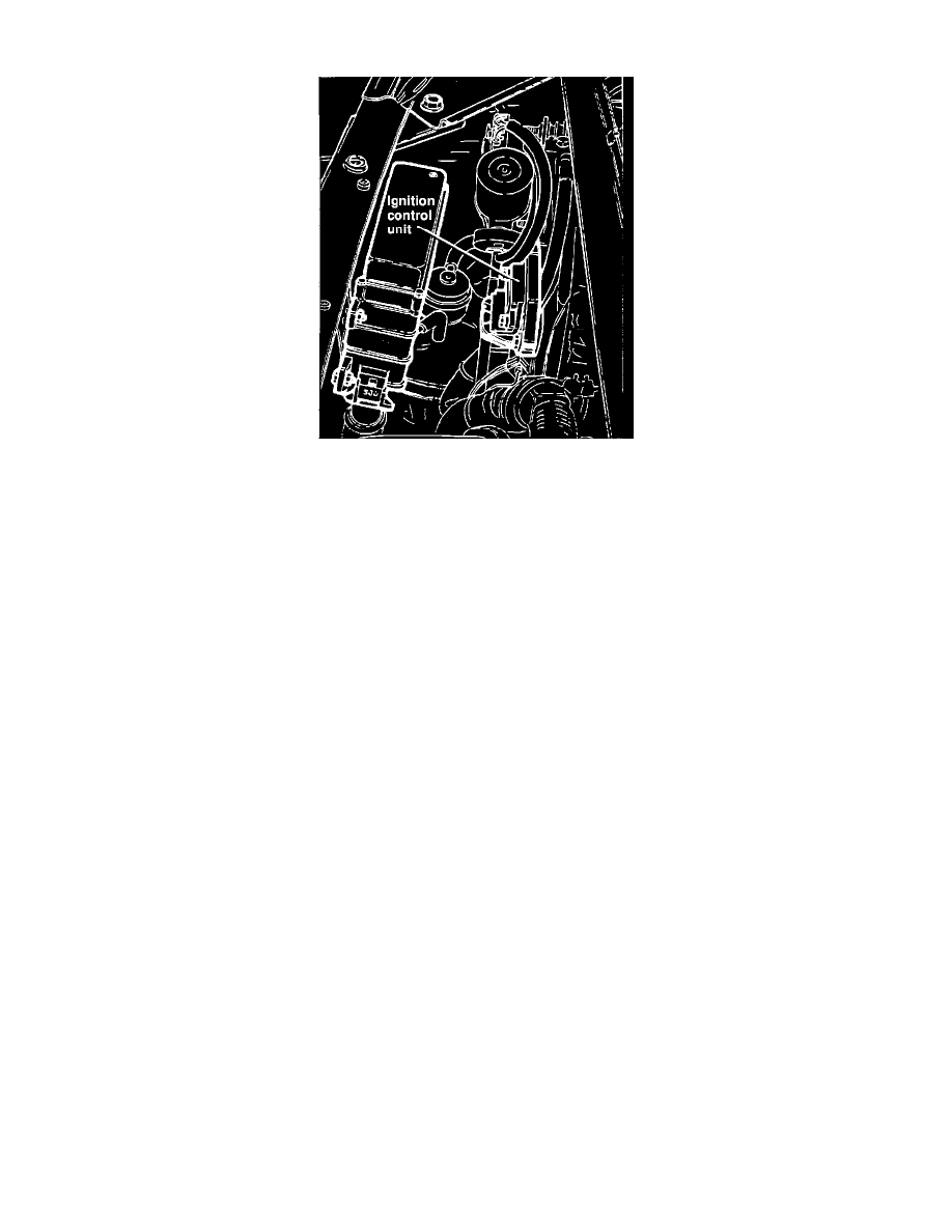
Fig. 83 Ignition Control Unit
The ECU, Fig. 83, receives signals from the knock sensor, fuel system ECU, and the Hall effect switch in the distributor. In the ECU, these signals are
analyzed and compared to the programmed values in the ECU's memory. The ECU then adjusts the ignition timing by applying signals to the ignition
system which opens the primary circuit of the coil and triggers the ignition spark.