
900 L4-1985cc 2.0L SOHC (1988)
Hall Effect Sensor: Description and Operation
Hall-Effect Sensor Construction
PURPOSE AND LOCATION
The hall-effect sensor supplies the ignition ECU with information regarding crankshaft position and speed and is located in the distributor.
CONSTRUCTION
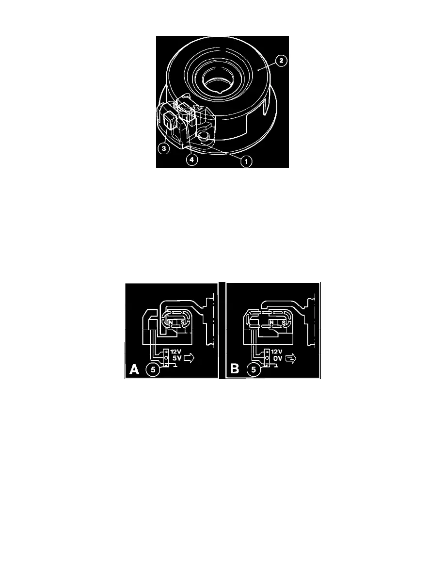
The hall-effect sensor (1) is a U-shaped element with an opening for the trigger rotor (2). The number of trigger vanes is equal to the amount of
cylinders in the engine.
The sensor consists of a hall-IC element (3) incorporating a hall-effect detector and a transistor amplifier. A magnet (4) with a three-pole
connector (5) is located on the opposite side of the rotor to the hall-IC element. The connector terminals are connected to a 12V supply (+) from
the control unit, a 5V reference signal (generated by the hall-IC element) and a ground (-) connection.
Hall-Effect Sensor Operation
OPERATION AND SIGNAL
A) In this position, the magnetic field is blocked by the trigger rotor vane and the hall-effect is absent. The hall-IC element registers a low or no
voltage, sending its 5V reference signal (O) to the ECU. The ignition ECU now senses no voltage drop and knows the trigger rotor is in its
"closed" position.
B) In this position, the magnetic field is opened by the opening in the trigger rotor and the hall-effect is generated. The hall-IC element registers the
voltage generated by the magnetic field, grounding the 5V reference signal (O) circuit. The ignition ECU now senses a voltage drop to 0V and
knows the trigger rotor is in its "open" position.
The signal from the hall-effect sensor varies therefore between 0 and 5 volts in the form of a square-wave (digital) signal.
To calculate the engine RPM, the ignition ECU uses the time duration from one signal change to the next, i.e. the smaller the time duration, the
higher the engine RPM.
To calculate the crankshaft position, the distributors basic setting is adjusted so it coinsides with the positive flank of the hall-effect sensor signal
(i.e. the wave generated when the trigger rotor blocks the magnetic field) a few crankshaft degrees before TDC.