
900 L4-1985cc 2.0L SOHC (1988)
Oxygen Sensor: Description and Operation
Electrical Description
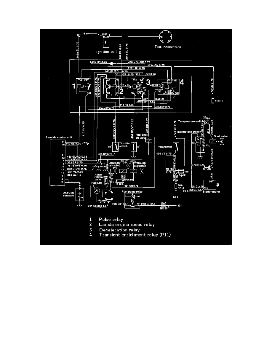
Fig. 74 Lambda System Wiring Diagram
The oxygen sensor provides one of several input signals that the ECU process to determine the proper air fuel ratio. Other inputs include engine RPM,
engine temperature, throttle position and air mass.
Current to the oxygen sensor control module is supplied by the combined regulating and fuel pump relay assembly. The oxygen sensor is connected to
control unit terminal 2 and grounded to the exhaust manifold. The oxygen sensor lead includes a suppressor harness which is connected to control unit
terminal 4. The throttle valve switch connects control unit terminals 5 and 7 at full throttle, providing a pulse relation with longer opening intervals for
richer mixtures.
A test circuit with a connector piece is included to enable pulse measuring equipment to be connected. The connector piece is located at the relay
holder and the cables run to terminal 17 (-) on the control unit and terminal 15 (+) in the primary circuit of the ignition system.