
900 L4-1985cc 2.0L SOHC (1988)
Steering Gear: Service and Repair
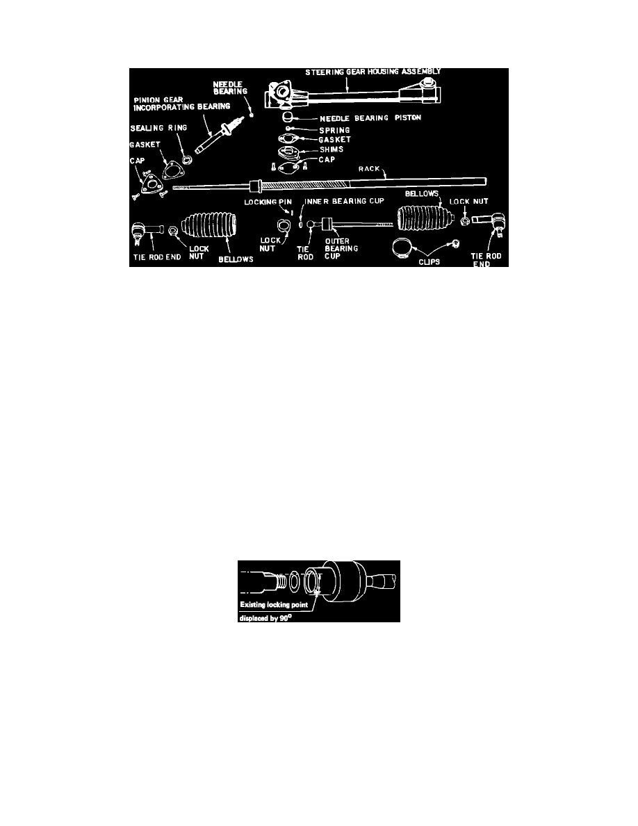
Manual Steering Gear Service
Fig. 1 Manual steering gear assembly exploded view.
1.
Loosen locknuts and remove tie rod ends, then open clips and remove bellows, Fig. 1.
2.
Remove tie rods with adjustable type ball joint as follows:
a. Drill out retaining pins to a depth of 3/8 in., using a 0.158 in. (4 mm) drill bit.
b. Remove outer bearing cup and locknut using spanner No. 8390197, or equivalent, and slip joint pliers.
3.
Remove tie rods with enclosed type ball joint as follows:
a. Support rack in vise and drill out retaining tab from groove using a 0.158 in. (4 mm) drill bit.
b. Clamp toothed end of rack securely, using protective covers to avoid damaging rack, and remove joint using spanner 8996472, or equivalent,
and a breaker bar. No load may be placed on pinion when removing or installing ball joint.
4.
Remove 2 bolts securing rack adjustment cap, and remove cap, gasket, shims, spring, and plunger, saving shims for reassembly.
5.
Remove pinion screws, pinion, cap, gasket, shims and upper bearing. Bearing is factory fitted to the pinion shaft and cannot be replaced
separately.
6.
Clean parts and lubricate with gear grease. Install lower pinion bearing.
7.
Install tie rod with adjustable type ball joint on pinion end of rack as follows:
a. Install locknut on rack and insert plastic cup in end of rack.
b. Fit ball of tie rod into plastic cup and thread outer bearing cup onto rack.
c. Tighten bearing cup so that a force of 1.6-7.2 ft.lbs. is required to move tie rod through full articulation. If it is not possible to obtain
adjustment specification, tie rod joint assembly must be replaced.
d. Tighten locknut to 35 ft.lbs. with spanner, while holding position of bearing cup with suitable pliers.
e. Drill new hole in for lock pin 3/8 in. deep using a 0.158 in. (4 mm) drill bit.
f.
Insert pin and secure by staking edge of hole in four places.
8.
Install tie rod with enclosed ball joint on pinion end of rack as follows:
Fig. 2 Positioning Locking Mark On Inner Ball Joint
a. Thread joint onto rack and torque to 80-94 ft.lbs., using spanner No. 8996472 or equivalent. If old joint is to be reused, previous locking
mark must be offset 90°. Install shim, Fig. 2, between joint and shoulder of rack.
b. Lock joint in position by staking shoulder of housing into rack groove, using a suitable punch.
9.
Insert rack in housing and install pinion with upper bearing and sealing ring and cap with gasket and shims, if equipped. If axial play exists with
pinion cap installed, pinion and upper bearing must be replaced as an assembly.
10.
Install plunger and cap without spring gasket and shims, tightening cap retaining bolts finger tight. If wrench is used to tighten retaining bolts,
cap will be deformed.
11.
Measure clearance between cap and housing using suitable feeler gauges.
12.
Assemble a shim pack, including cap gasket, using micrometer for measurement. Shim pack should be 0.002-0.006 in. thicker than clearance
measured in step 12, to allow clearance between plunger and cap.
13.
Remove cap and install plunger spring, shim pack with gasket, and reinstall cap.
14.
Check that rack does not bind or stick in any position. Rotating torque for properly adjusted assembly is 0.83-1.5 ft.lbs., measured using