
9000 L4-1985cc 2.0L DOHC Turbo EFI (1987)
ABS Main Relay: Diagram Information and Instructions
Units
Using the Sub-System Wiring Diagram
An example of two spreads for a sub-system - in this case the interior lighting with time delay - is shown below, together with explanations of the
designations used, etc.
Unless otherwise specified, switches are shown in un-actuated condition and relays in de-energized condition.
In the sub-system diagrams, every subsystem is generally shown from the relevant fuse in the electrical distribution box, up to each consumer or
sub-system, and then to the earthing point (chassis connection).
The supply to each fuse is shown separately in the section entitled "Positive supply", which also deals with the electrical distribution box, ignition
switch, etc.
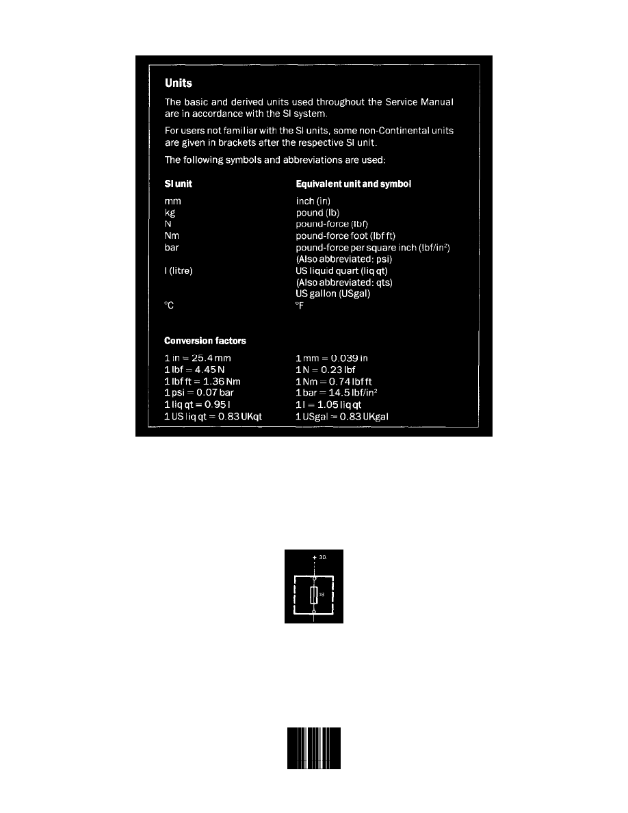
If +30, for instance, is written above a fuse, the supply from the battery to the respective fuse is shown in the section entitled "Positive supply +30".