
9000 L4-2290cc 2.3L DOHC Turbo EFI (1992)
Engine Control Module: Connector Views
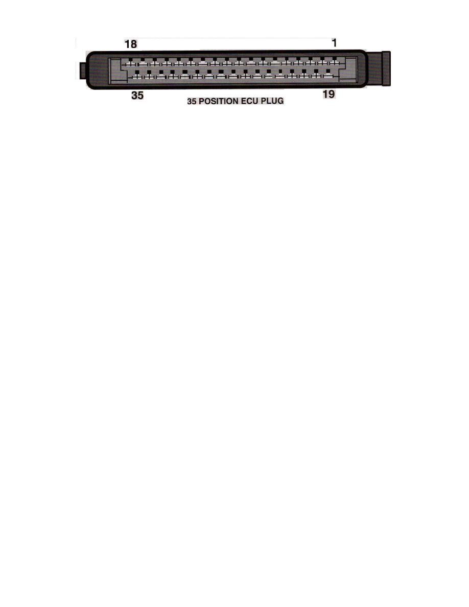
35 Position ECU Plug
Pin Layout
System
LH-Jetronic
Location
Kick panel passenger side
Terminal ID
1 - Ground
2 - Closed throttle
3 - From turbo APC unit pin 31
4 - Lighting relay
5 - Ground
6 - Air Mass Meter Supply
7 - Air Mass meter Load
8 - Air Mass Meter Burn-off
9 - Main Relay Supply
10 - Full load throttle
11 - N/A
12 - Diagnostic Connector
13 - Coolant Temperature Sensor
14 - Fan relay
15 - ISC valve
16 - Diagnostic Connector
17 - Ground
18 - Injector Driver (4)
19 - N/A
20 - Fuel Pump Relay Control
21 - Main Relay Control
22 - Trip computer
23 - Air mass meter ground
24 - O2 Sensor Signal
25 - Output to APC unit pin 36
26 - Shift indicator
27 - Canister Solenoid Control
28 - From APC unit pin 26
29 - Coding
30 - Idle speed switch NT
31 - Trip computer
32 - N/A
33 - ISC valve
34 - Speedometer
35 - Ignition Switch