
9000 Aero L4-2290cc 2.3L DOHC Turbo EFI (1996)
Switches, Relays And Components
Unless otherwise indicated, switches and relays are represented in their unactivated and unenergized state.
When the box round the component is drawn with a solid line, the whole component is shown.
When the box round the component is drawn with a broken line, only part of the component is shown.
The components are designated by a serial number and one or more letter suffixes which indicate location or variant. Locations are indicated by
upper-case (capital) letters, e.g. 298FL, while variants are indicated by a lower-case (small) letter, e.g. 47a. The following abbreviations for the
various locations are used:
C =
Centre
D =
Driver side
F
=
Front
H =
Hatch (tailgate)
P
=
Passenger side
R =
Rear
LH =
Left Hand
RH =
Right Hand
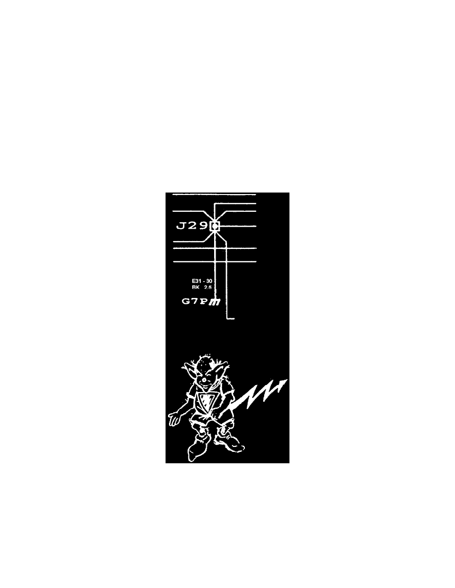
Symbols: Crimped Connections
Crimped Connections
To reduce the number of connectors, the car's wiring contains several crimped connections. The symbol for these connections in the wiring
diagram is shown in the above image.
Data Link Connector Information
To facilitate testing the different electronic systems, the car is equipped with a number of special data link connectors and test sockets.
These connectors have the following component numbers:
444
Saab Trionic test socket. Small
round black connector beside the