
9000 Aero L4-2290cc 2.3L DOHC Turbo EFI HO (1997)
Ventilation Fan: Component Location
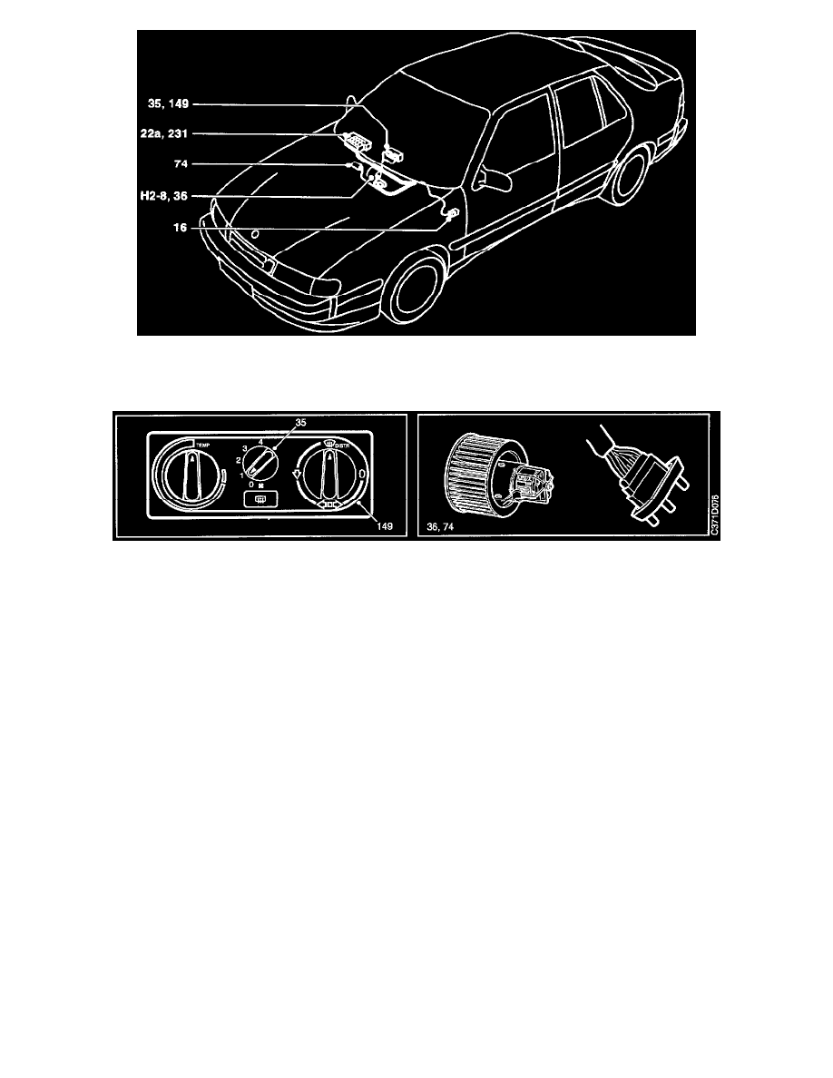
COMPONENT LOCATION VIEW
Ventilation Fan: Component ID
COMPONENT ID
22a
Fuse board behind the access panel in the glove box.
35
Switch, ventilation fan, on the control panel for heating and ventilation.
36
Motor, ventilation fan, in the fan housing between the evaporator casing and heater housing.
74
Resistor, ventilation fan, in the fan housing frame beside the cable connection.
149
Main switch, fan, on rear of the control panel for heating and ventilation.
231
Distribution terminal (+54 circuit), in main fuse box behind the glove box.
2-Pin connector
H2-8
Next to the ventilation fan motor.
Grounding Points
G2
Grounding point, battery tray, on the left-hand wheel housing.
DESCRIPTION OF OPERATION
Current is supplied from fuse 6 to main fan switch 149 and on to ventilation fan switch 35. The main switch is controlled by the air distribution
control and breaks the circuit when the control is in position 0.
The fan selector switch, which controls fan motor 36 across resistor 74, can be set to four fan speeds. In position 1, the entire resistance is
connected, which gives the lowest fan speed. In position 4, the resistance is bypassed, which gives the highest fan speed.
The resistor is equipped with a fuse which blows in the case of an overload.
FAULT DIAGNOSIS HINTS
The ventilation fan is activated when the ignition switch is turned to the Drive position.
1. Inspect fuse 6 and check that it is supplied with current.
2. Check the current supplied to switch 35 and main switch 149.
IMPORTANT