
9000 CSE L4-2290cc 2.3L DOHC Turbo EFI (1995)
581
Electrically operated vacuum valve
582
Aerial, remote control unit, anti-theft alarm
584
Relay, secondary air injection control valve
585
Pressure sensor, EVAP
586
Control module, Motronic
587
Control module, Motronic
588
Solenoid valve, EVAP shut-off
589
Control module, Saab Trionic OBDII
590
Accelerometer
592Fa
Front heated oxygen sensor, 4-cyl, OBDII
592Fb
Front heated oxygen sensor, cylinder bank 1, V6, OBDII
592Ra
Rear heated oxygen sensor, 4-cyl, OBDII
592Rb
Rear heated oxygen sensor, cylinder bank 1, V6, OBDII
593F
Front heated oxygen sensor, cylinder bank 2, V6, OBDII
593R
Rear heated oxygen sensor, cylinder bank 2, V6, OBDII
How to Read and Use Wiring Diagrams
SYMBOLS USED IN THE WIRING DIAGRAMS
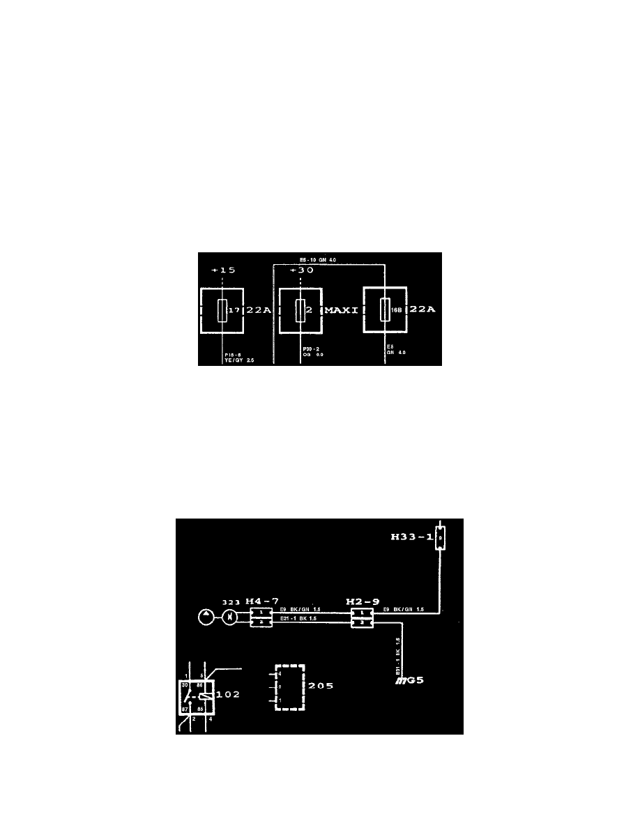
Symbols: Fuses
Fuses
In the wiring diagrams, every subsystem is generally shown from the relevant fuse in the main fuse box up to the relevant component or
components and on to the grounding point or direct chassis connection.
The power supply to each fuse is shown separately in the section headed "Power supply systems", which also covers the car's main fuse box,
ignition switch, etc.
Example:
If the supply to a fuse comes from the +30 terminal, the feed to the fuse in question is found in the "Power supply, +30 circuit".
Symbols: Grounding Points
Grounding Points
Most of the car's grounding points have a component number consisting of a letter and a number, e.g. G2 or G29. The locations of the grounding