
9000 CSE L4-2290cc 2.3L DOHC Turbo EFI (1995)
Engine Control Module: Component Tests and General Diagnostics
Control Module Connections, Test Readings
TEST READINGS, CONTROL MODULE CONNECTIONS
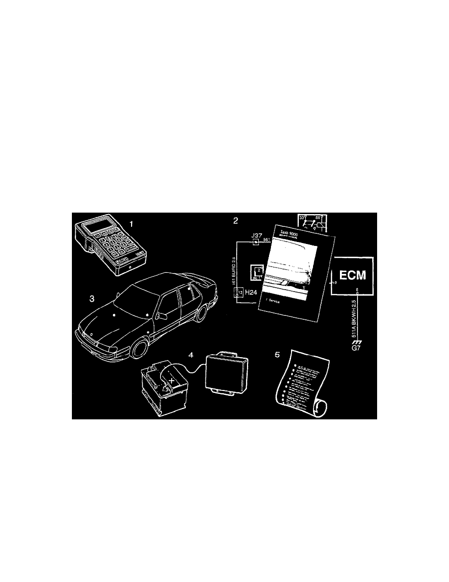
Points To Remember:
-
Readings should be taken via a Breakout Box (BOB) connected between the control module and the control module connector.
-
Several voltage levels must be regarded as guiding values. Use your common sense when judging whether an instrument reading is correct or
not.
-
If any reading is incorrect, use the appropriate wiring diagram to ascertain which leads, connectors or components ought to be checked more
closely.
-
The references "Principle of Operation" and "Fault" in the table relate to the principle of operation of the component concerned and to the
relevant fault diagnosis schedule containing a detailed description of the diagnostic procedure to be followed.
-
All test readings are in respect of a warmed-up engine.
-
Unless otherwise specified, the ignition should be switched on.
-
Indicated readings refer to calibrated FLUKE 88/97.
For testing, refer to Diagnostic Charts / Test Readings, Control Module Connections. See: Testing and Inspection/Pinout Values and Diagnostic
Parameters
Before Control Module Replacement
BEFORE REPLACING A CONTROL MODULE
When all the checks have been carried out in accordance with the diagnostic procedures programme for the diagnostic trouble code concerned or
through manual fault diagnosis without any fault having been detected, it is natural to assume that the control module is at fault.
You should carefully run through the following points before finally identifying the Trionic control module as the cause of the fault.
1. Check once more that all the items for checking in the fault diagnosis procedure for the relevant diagnostic trouble code have been carried out.
2. Study the wiring diagram of the relevant circuit and make sure you know how it works.
3. Check all grounding points. If you have already done this, do it once more. Check that power ground and sensor are mechanically and electrically
separated.
4. Check the voltage supply to the control module.
5. Experience of model year 1993 shows that 80% of all Trionic control modules returned for repair under warranty were in perfect working order.
Do not fit replacement control modules unnecessarily.
Control modules that are replaced without reason represent a sizeable cost item for Saab automobile and Saab dealers. Think through likely causes