
9000 Hatchback L4-2290cc 2.3L DOHC Turbo EFI (1994)
3. Acceleration Slip Regulation (ASR)
The ETS control module is mounted on a bracket under the LH front seat. On automatic transmission cars with an anti-spin system, an ASR
control module is mounted on top of the ETS control module.
COMFORT SYSTEMS
4. Cruise Control
5. Central Locking
The control module for the Cruise Control and central locking systems is mounted on a bracket at far right under the dashboard.
SAFETY SYSTEMS
6. ABS or TC/ABS
The ABS or TC/ABS control module is mounted on the battery tray.
7. Airbag
The airbag control module is located on a bracket in the front part of the centre console inside the cabin under the dashboard.
8. Anti-theft alarm
The control module for the anti-theft alarm in located inside the cabin behind the glove box and knee shield on the RH side behind the dashboard.
Data Link Connector Information
Data Link Connector, Below Rear Seat
DATA LINK CONNECTORS AND TEST SOCKETS
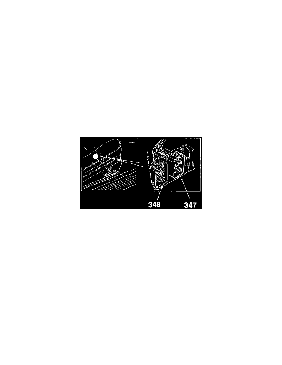
To facilitate testing its various electronic systems, the car is equipped with a number of special data link connectors and test sockets.
These sockets have the following component numbers:
Number
System
347
Data link connector, engine electronics
348
Data link connector, car electronics
444
Saab TRIONIC test socket - a small black round connector beside the TRIONIC control module (for production only)
General Information
GENERAL
The car's +12 V power supply is distributed to the various consumers via four fuse boxes, one behind the glove box, one in the engine bay by the
LH headlamp, one for the secondary air injection pump in the engine bay and one for the ABS brakes in the engine bay on the bulkhead partition.
Most of the fuses and relays are located in the fuse boxes.
The fuses are of blade type and, in combination with the connectors used, cause a lower voltage drop than the earlier type. They are also more
resistant to corrosion.
Colour coding of blade fuses:
Fuse
Colour
5A
Light brown
7.5A
Dark brown
10A
Red