
9000 Hatchback L4-2290cc 2.3L DOHC Turbo EFI (1994)
3. Slide the rubber gaiters towards the rack-and-pinion housing to expose the groove in which it seals.
4. Measure dimension C. Dimension is the distance between the locknut and the edge of the groove for the gaiter, must never be allowed to exceed
140 mm (5.51 inch).
5. Repeat steps 2 - 4 on the other side of the car.
6. Compare measurement the two values of dimension C. The difference between the two sides of the car must not exceed 2 mm (0.079 inch). The
main reasons that dimension C on either side of the car must not vary by more than 2 mm (0.079 inch) are:
^
To avoid. undesirable over-steer when cornering.
^
To avoid exceeding the maximum permissible working angle of the CV joints.
^
To prevent the wheel from rubbing against the wing liner.
7. Adjust, if necessary.
NOTE: The toe-in must be checked after any adjustment of the track rod length.
8. Slide the rubber gaiter back into the groove.
9. Refit the clip.
10. Repeat steps 8 - 9 on the other side of the car.
11. Check the position of the steering wheel.
Camber
Camber is preset during production and is not adjustable. If front camber is not within specified limits, check and replace defective components.
Caster
Caster cannot be adjusted. If setting is not within specified limits, defective components must be replaced.
Kingpin Inclination
Kingpin inclination is preset and not adjustable. If kingpin inclination is incorrect, but camber is satisfactory, check for a faulty steering swivel
member. Replace if necessary.
Toe-In
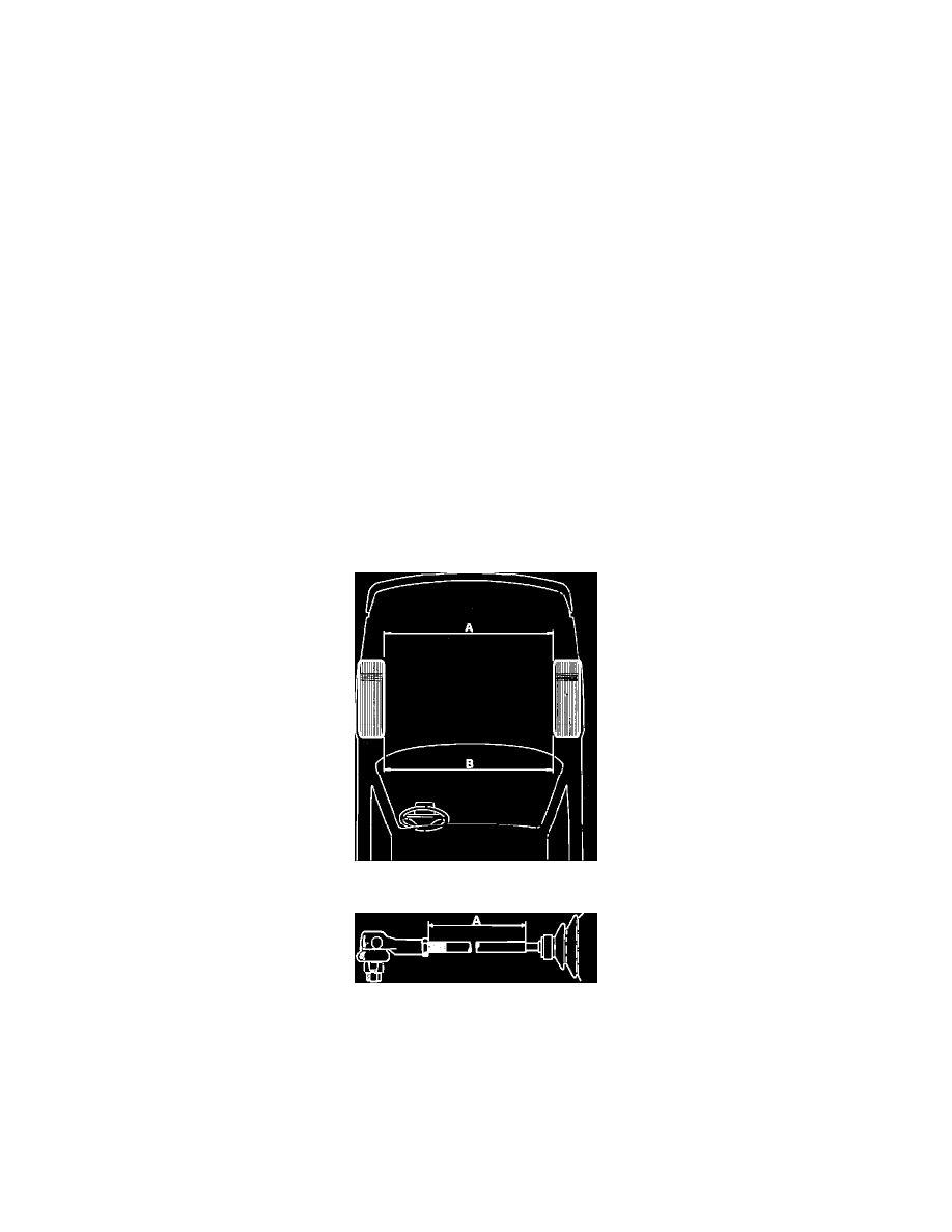
Fig. 2 Toe-in Adjustment Vehicle Position
Fig. 3 Toe-in Adjustment
1.
Roll vehicle straight forward on level floor and stop without using brakes.
2.
Take a reading at dimension ``A,'' Fig. 2, using a toe-in gauge between the front wheel rims level with axle. Mark measurement parts with chalk.
3.
Roll vehicle forward until chalk marks are level with, but behind, axles and take reading of B, Fig. 2. Any necessary adjustment is made by
altering length of tie rod.
4.
Remove rubber bellows to track rod retaining clip.
5.
Push rubber bellows toward steering gear housing to expose groove in which bellows seals.
6.
Measure distance A, Fig. 3. Distance A should not exceed 3.94 (100mm) on 900 models, or 5.51 inches (140mm) on 9000 models.
7.
Perform steps 4 through 6 on opposite side of vehicle, then compare measurements calculated at each side of vehicle. Difference between
measurements must not exceed .079 inch (2mm).