
9000 Hatchback L4-2290cc 2.3L DOHC Turbo EFI (1994)
PUMP OPERATION
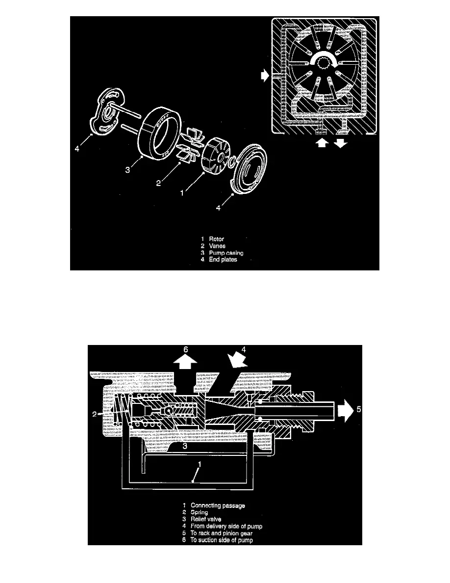
The pump consists of a rotor (1) including a number of slots, a vane (2) for for each slot, a pump casing (3) and two end plates (4) with intake and
output passages for the pump element.
The oval form of the pump casing causes increasing and decreasing volume between the pump vanes. This occurs twice for each revolution of the
rotor. The intake ports lead to the space where the volume increases and the outputs lead from the space where the volume decreases, thereby
achieving a pumping action. In addition to the vanes being thrown outwards by the centrifugal force, they are pushed outwards against the casing by
the pressure of the fluid flowing through the slots at the bottom of the vanes.
PRESSURE AND FLOW CONTROL