
900 S Convertible L4-2290cc 2.3L DOHC (1996)
Engine Control Module: Description and Operation
Description Of Operation, Control Module Power Supply
Engine Control Module Power Supply
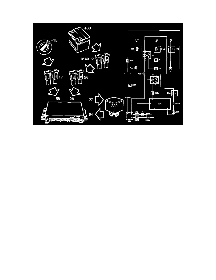
+30:
Current (+30 circuit) is supplied to pin 26 of the control module via MAXI fuse 2 and fuse 28.
The control module uses current from the +30 circuit for its memory.
The engine will not start unless power is supplied via the +30 circuit.
+15:
Current (+15 circuit) is supplied via fuse 17 to the anti-theft alarms control module which (if not blocked by the alarm) supplies it in turn to pin 58 of the
Motronic control module.
When current (+15 circuit) is applied to pin 58 the control module is activated and grounds pin 27, causing the main relay to operate. The main relay
supplies the control module with battery positive voltage (B+) on pin 54.
The engine will not start without current from the +15 circuit or if no current is applied to pin 54 of the control module.