
900 S Coupe L4-2290cc 2.3L DOHC (1995)
Engine Control Module: Pinout Values and Diagnostic Parameters
Points to Remember
SOME IMPORTANT POINTS TO REMEMBER:
-
Readings must be taken with a Breakout Box (BOB) connected between the control module and the control module connector.
-
Several voltage levels must be regarded as guiding values. Your common sense should tell you whether a reading is correct or not.
-
If any test reading is obviously wrong, use the wiring diagram to trace the leads, connectors or components which you consider ought to be
checked more thoroughly.
-
References in the tables at "Test Readings" refer to the location at which the principle of operation of the signal concerned is described, and
also to the fault diagnosis schedule containing a complete description of the diagnostic procedure to be followed.
Test Reading Charts
Control Module Connections
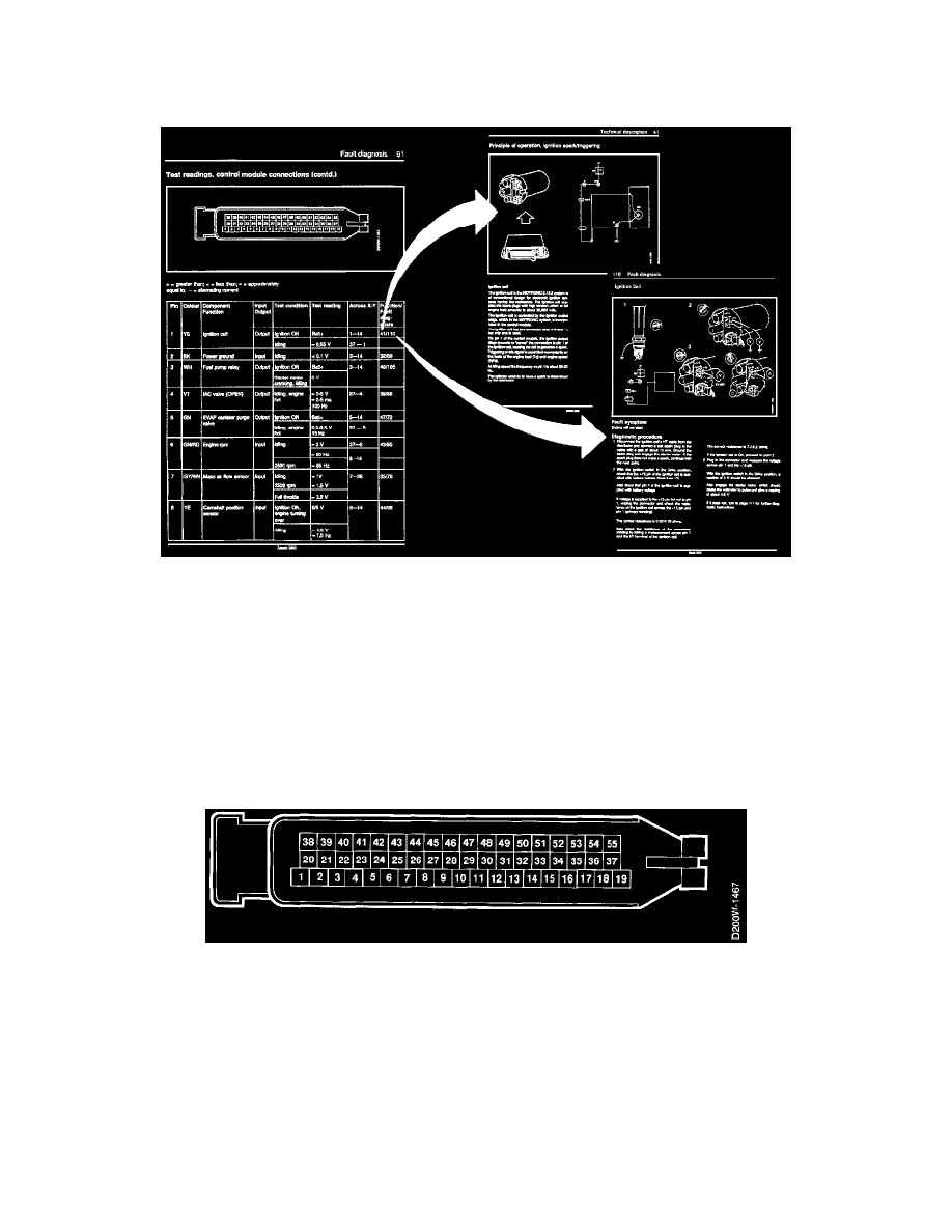
TEST READINGS, CONTROL MODULE CONNECTIONS
Scope
Test readings and instructions for measuring signals and signal levels on the MOTRONIC control module are given in the following charts.
NOTE: Symbols in the following charts, > = greater than; < = less than; ~/~ = approximately equal to; ~ = alternating current.