
900 S Hatchback L4-2290cc 2.3L DOHC EFI (1997)
Crankshaft Position Sensor: Description and Operation
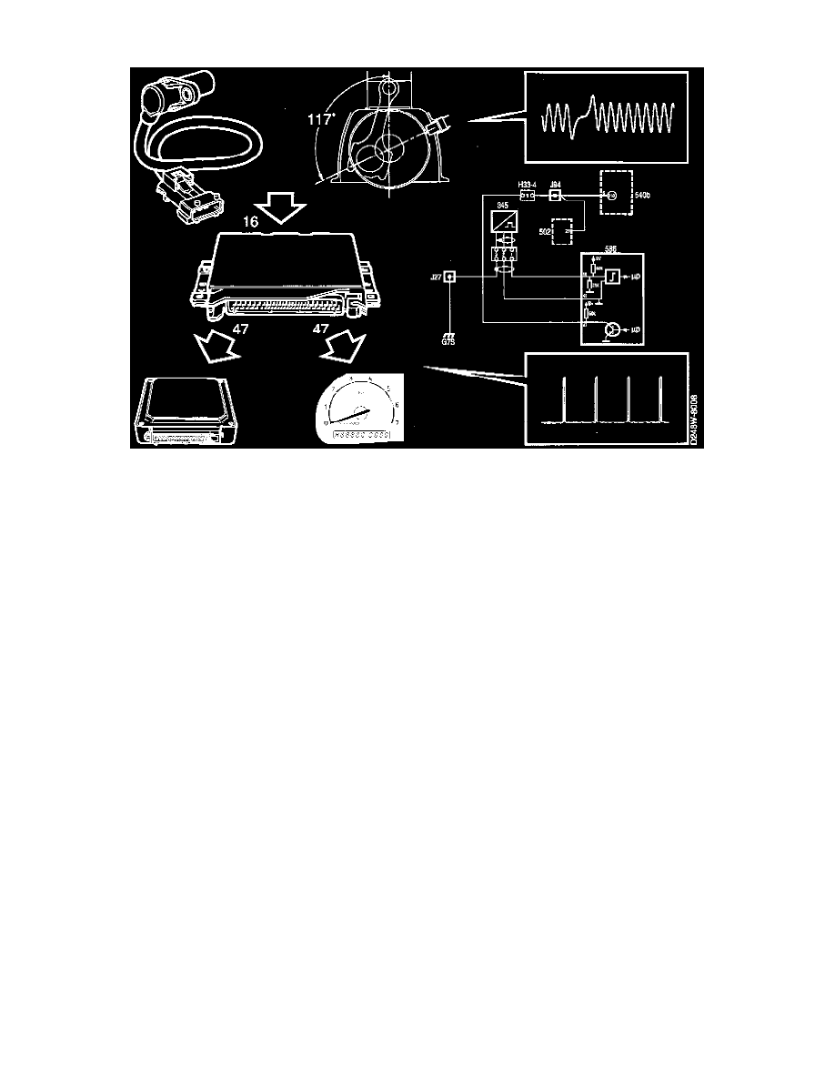
Information on the position and speed of the crankshaft is sent from the crankshaft position sensor to pin 16 of the control module. The sensor is
connected to ground via pin 43 of the control module.
Mounted on the crankshaft is a slotted ring with 58 ribs. Of inductive type, the sensor is mounted on the wall of the engine crankcase. The distance
between the slotted ring and the sensor is 0.4 - 1.3 mm and it is not adjustable.
The sensor acts as a small alternator and generates a sine-wave a.c. voltage. The voltage and frequency signals from the crankshaft position sensor vary
with engine speed. Sensor input at idling speed is 5-10V a c., 870 Hz, and at 2500 rpm it is 15-20V a C., 2400 Hz. The frequency is of interest to the
control module as it is directly proportional to engine speed. By measuring the frequency of this current, the control module can determine engine rpm.
Two ribs are missing on the slotted ring after the 58th rib.
When the first rib passes the sensor, the control module knows that the crankshaft is 117° before top dead centre (BTDC) for cylinder No. 1. By
measuring the two missing ribs the control module can determine the position of the crankshaft.
The control module mainly uses engine speed and the crankshaft position as a basis for calculating ignition timing, injection time, injection duration and
for idle speed control.
Fuel injection is cut off when engine speed exceeds 6400 rpm.
As soon as the control module receives signals from the crankshaft position sensor it grounds the fuel pump relay, causing it to operate.
Should the sensor fail to work or in the event of a break in the circuit (no continuity), the engine will not start.
The sensor's resistance is 860 ±90 ohms.