
900 S Hatchback L4-2290cc 2.3L DOHC EFI (1997)
Engine Control Module: Testing and Inspection
General
Test readings and instructions for measuring signals and signal levels on the Motronic control module are given in the following charts
Remember:
^
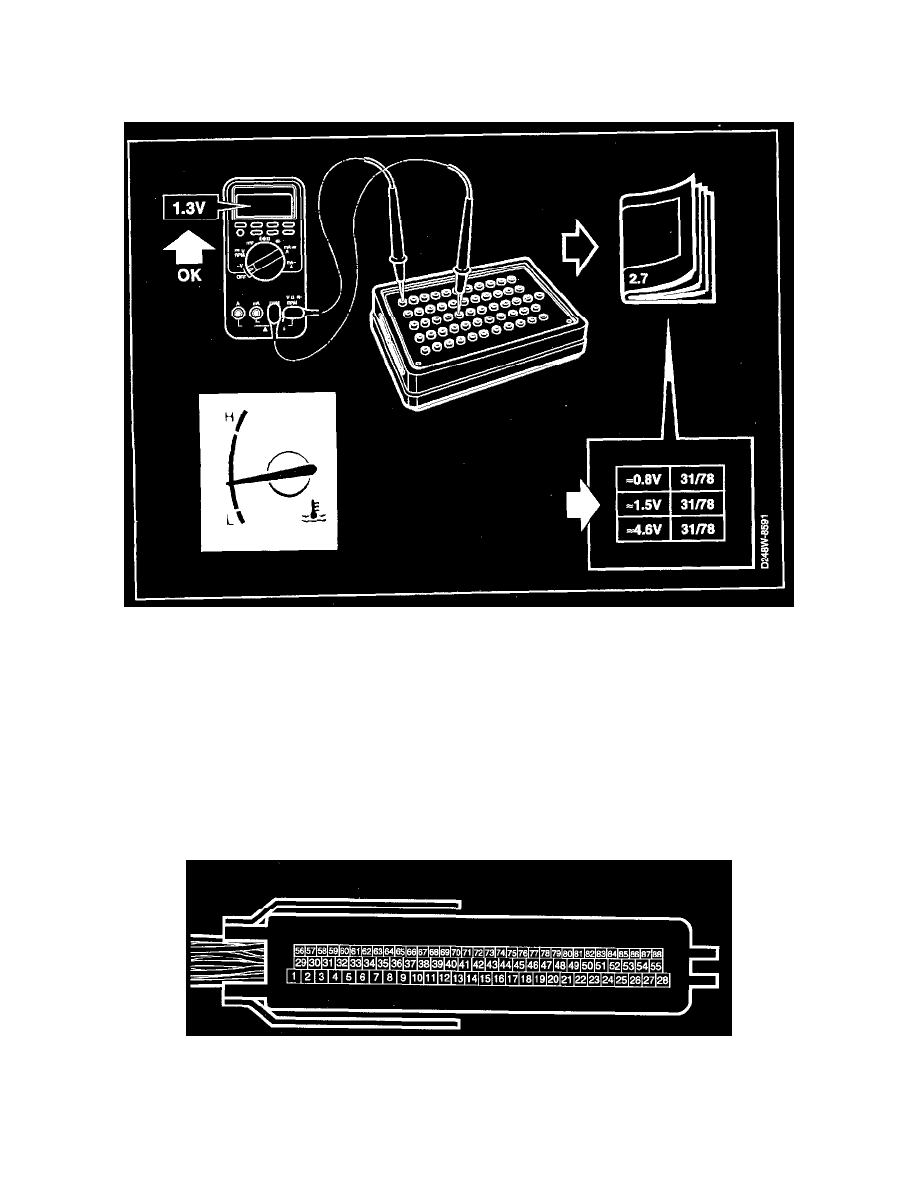
Readings should be taken via the Breakout Box (BOB) connected between the control module and the control module connector.
^
Several voltage levels must be regarded as standard values. Use your common sense when judging whether a reading is correct or not.
^
If any reading is incorrect, use the wiring diagram to ascertain which conductor, connector or component requires further testing.
^
The "Function" references in the tables refer partly to the description of operation of the relevant signal and partly to the fault diagnosis schedule
with a complete description of the diagnostic procedure to be followed.
^
All test readings are for an engine at normal operating temperature.
^
Unless otherwise stated, the ignition should be switched ON.
^
The test readings in the charts refer to a calibrated FLUKE 88/97.
> = greater than; < = less than; approx = approximately equal to; ~ = alternating current ( LP:LOGIC PROBE P = select pulse; p = visible pulses).