
900 S Sedan V6-2498cc 2.5L DOHC (1995)
5
If the leads are OK, the fault is probably in one of the control modules.
6
Plug in the ICE control module connector and repeat points 2 and 3 while grounding connector pin 4 (12p-1 main instrument display panel 1) or
connector pin 7 (main instrument display panel 2) at the same time.
The voltage reading obtained should be 0 V with the ignition switch "ON" and 12 V with it "OFF".
If the voltage reading is OK, the fault is probably in the main instrument display panel. Continue fault diagnosis as described in "Main instrument
display panel". See: Instrument Panel, Gauges and Warning Indicators/Instrument Cluster / Carrier/Testing and Inspection
If the voltage reading is not OK, continue on "Before Changing an Electronic Control Module".
Checking the idling speed increase (MOTRONIC 2.10.2 only)
1
Plug in the ISAT scan tool and select "READ FAULT CODES" from the menu. If any trouble codes are present, continue in Trouble Code Tables.
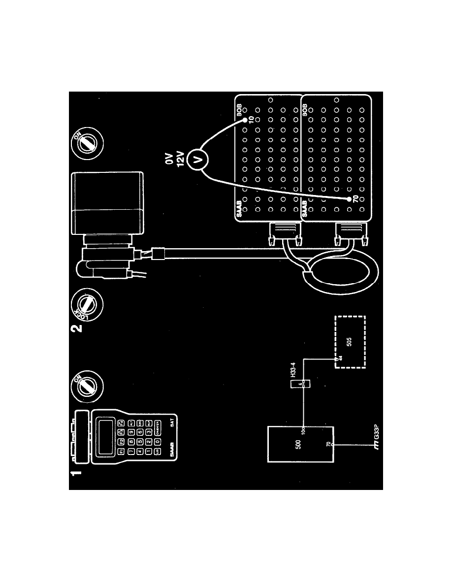
2
Connect a BOB and take voltmeter readings across connector pins 10 and 70. Check the increase in idling speed by selecting "ACT. OTHER
FUNCT" from the menu and then "IDLING INCREASE".
Read the voltmeter to see whether the voltage drops to about 0 V when the ignition switch is "ON" and rises to about 12 V when it is "OFF".