
900 S Sedan V6-2498cc 2.5L DOHC (1995)
6
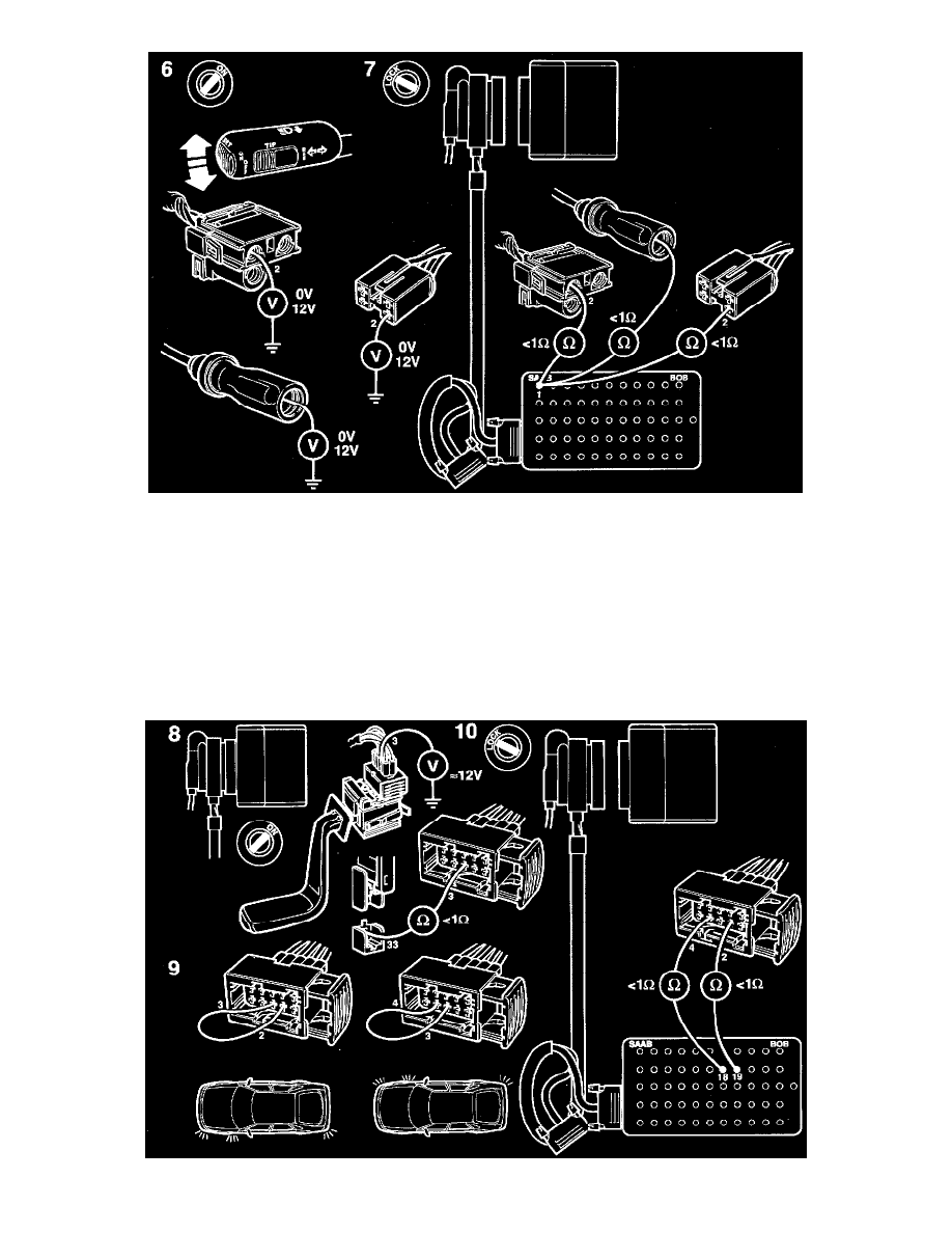
Activate the direction indicator switch and check the power supply to the direction indicator lamps by taking readings as follows:
-
between pin 2 of the connector for the front direction indicator lamps and a good grounding point.
-
between the left-hand side direction indicator connector (yellow/black lead) and a good grounding point.
between the right-hand side direction indicator connector (green/black lead) and a good grounding point.
-
between pins 2 (left-hand) and 4 (right-hand) of the rear direction indicator lamp connectors and a good grounding point.
The voltage readings should change between 0 V and 12 V.
7
If they do not, check the wiring for continuity/ shorting as follows between Integrated Central Electronics (ICE) module connector pins 1
(left-hand) and 48 (right-hand) and:
-
pin 2 of the connector for the front direction indicator lamps.
-
the connector for the side direction indicators (yellow/black (LH) and green/black (RH) leads).
-
pins 2 (left-hand) and 4 (right-hand) of the connector for the rear direction indicator lamps.
8
Check the power supply to the direction indicator switch by taking a voltmeter reading between pin 3 of the switch connector and a good